The Internet is not a single invention but the result of thousands of years of human efforts to communicate more effectively. Every major breakthrough—from spoken language and writing to the printing press, telegraph, telephone, radio, and computers—solved a communication problem such as distance, speed, scale, cost, or reliability. The Internet unified these innovations into one global communication system.
At its core, the Internet does not move websites, videos, or emails—it moves information. Information becomes useful only when interpreted within the right context, and computers process it without understanding its meaning. To make this possible, every form of information—text, images, audio, video, and software—is converted into a common digital representation.
Computers use binary (0s and 1s) not because mathematics requires it, but because electronic hardware can reliably distinguish between two stable physical states. Bits combine into bytes, bytes represent numbers and characters, and standardised encodings such as ASCII and Unicode allow computers worldwide to exchange information consistently.
However, binary itself never travels across the Internet. It is translated into electrical, optical, or radio signals, transmitted through physical media, and reconstructed back into binary by the receiving device. This layered process—from human ideas to information, binary representation, physical signals, and back to meaningful information—forms the foundation of all modern computing and networking.
Understanding these first principles prepares the reader for the next stage: learning how physical signals travel through networks and eventually become packets, protocols, and the global Internet.
ENGINEERING ADVANCE: You have now mastered the fundamental physics of data transmission. To see how these binary streams are packaged into hardware-parsed frames and routed globally, proceed to Volume II: Network Architecture & Protocols to initiate your protocol-level deep dive.
[ Traditional Textbook ] ──> Static overview of historically disconnected events.
[ TechZero Interface   ] ──> A cognitive map tying human scaling bottlenecks
                              directly to modern protocol architecture.
Why This Chapter Matters
Every structural component of modern networking—from the frame headers in Ethernet to the retransmission timers in TCP—exists to solve an ancient problem: how to move information across space and time without corruption. We do not study history to memorize dates; we analyze it to understand the origin of systemic constraints. This chapter traces how humanity systematically dismantled the limits of distance, throughput, and latency, building the cognitive infrastructure that made the Internet inevitable.
30-Second Smart Summary
The Internet is not a product of the computer age; it is the ultimate unification of human communication architectures. Every historical leap—from spoken dialect to electricity—resolved a physical constraint:
Telegraphy broke the link between data velocity and physical transport velocity ($v \approx c$).
The Internet unified all distinct media types into a single, software-defined network of networks.
Learning Objectives
Deconstruct how physical constraints (distance, time, cost) forced architectural shifts in human tracking systems.
Map historical communication breakthroughs directly to their modern computer networking counterparts.
Analyze the operational bottlenecks of store-and-forward networks using the historical postal/telegraphic matrix.
Historical Background
For 99% of human existence, the velocity of information was perfectly bound to the velocity of a physical object. If a message had to cross an ocean, it moved at the speed of a sailing vessel. If it had to cross a continent, it moved at the speed of a galloping horse. Information was heavy, slow, and bound to the physical constraints of human transportation networks.
[ Human Messengers ] ──(Bounded by physical velocity)──> [ Max Speed = Horse/Ship ]
[ Electrical Pulse ] ──(Decoupled from physical mass)──> [ Max Speed = Speed of Light ]
The realization that information could be isolated from physical mass is the exact foundation upon which all computer science rests. The transition occurred over distinct structural iterations:
The Dawn of Human Communication & Spoken Language
Before structured language, individual human knowledge suffered from an absolute exit timeout. Insights could not easily scale past physical sight lines or immediate tribal units. Spoken dialect established the first dynamic protocol suite, standardizing semantic audio tokens so that individual intelligence could aggregate into structural collective intelligence.
Spoken language lacked persistence; it vanished the moment the acoustic wave decayed. Human memory was volatile memory ($RAM$). The invention of writing (such as Sumerian cuneiform c. 3200 BCE) introduced the first persistent storage layer ($Non-Volatile Disk$). It decoupled information from the physical presence of the transmitter, allowing ideas to outlive human lifespans.
The Printing Press & Organized Postal Networks (Broadcasting & Routing)
If writing provided persistent data storage, Gutenberg’s printing press (c. 1450) created the first high-throughput replication engine. It dramatically lowered the cost per megabyte of information distribution, enabling mass broadcasting. Concurrently, empire-wide postal routes established the initial concepts of packet routing, using discrete relay stations as early intermediate nodes to optimize transit paths across massive physical distances.
Core Concepts & Deep Dive: The Velocity Split
==================================================================================
           THE HARD VELOCITY FRONTIER: SEPARATING DATA FROM TRANSPORT
==================================================================================
  POSTAL ERA (Store & Forward Physical Layer)
  [Sender] ──> [Letter Box] ──> [Horse/Train Transit] ──> [Sorting Hub] ──> [Receiver]
  * Latency: Days to Weeks  |  Throughput: High (Bulk physical letters)

  TELEGRAPHIC ERA (Speed-of-Light Pulse Layer)
  [Sender] ──> [Key Switcher] ──> ==== (Copper Wire / Current Pulse) ==== ──> [Receiver]
  * Latency: Milliseconds   |  Throughput: Minimal (Discrete coded characters)
==================================================================================
The mid-nineteenth century introduced the most disruptive architectural pivot in communication history: the telegraph. By modulating electrical current through copper wire, engineers achieved near-instantaneous long-distance messaging. This was the birth of telecommunications—the functional separation of information from physical matter.
Technical Blueprint: The Morse Code Protocol
Morse code was the world’s first widely deployed variable-length digital character encoding system. It parsed human alphabet characters into discrete binary-like states: short signals (dots) and long signals (dashes), separated by precise silent intervals.
To optimize the transmission channel, the protocol was designed around character frequency. The letter “E”, which is the most common letter in the English language, was assigned the shortest possible token: a single dot (.). Conversely, less frequent letters like “Q” received longer, higher-overhead sequences (--.-).
Modern compression algorithms like Huffman Coding—which systems like JPEG and HTTP/2 HPACK leverage to optimize network bandwidth—use this exact architectural premise: map the most frequent data inputs to the smallest physical bit representations.
Engineering Perspective
Network engineers look at human history as an evolution of structural constraints. When we evaluate early telecommunications, we see the prototypes for structural network layers:
Standardized Line Codes: Translating abstract concepts into physical medium states (Morse code flashes/pulses mapping directly to modern line coding like NRZ or Manchester encoding).
Intermediate Relay Topologies: Early telegraph stations acted exactly like modern network repeaters and store-and-forward switches—interpreting a degraded, noisy incoming signal, re-amplifying it, and forwarding it down the next physical wire line.
Real-World Case Study: The Telegraph vs. Postal Mail
In 1860, the fastest transcontinental communication system in the United States was the Pony Express, a highly optimized postal layout utilizing sequential horse-and-rider relays. Moving a physical text bundle from the Atlantic coast to the Pacific coast required a minimum of 10 days.
In October 1861, the First Transcontinental Telegraph line was completed. The transition was immediate:
The system throughput dropped dramatically (bulk paper letters could carry thousands of words, while telegraph lines were restricted to slow, character-by-character key entry), but the absolute network latency dropped by five orders of magnitude ($10\text{ days} \rightarrow \text{seconds}$). For high-priority institutional data like capital transactions, military alerts, and geopolitical orders, the latency reduction completely transformed global operations.
Common Misconceptions
Myth: The Internet is a fundamentally distinct ecosystem built entirely from scratch during the late 20th century.
Reality: The Internet is an architectural iteration. The rights-of-way, transoceanic routes, structural topologies, and core switching concepts were directly inherited from the early global telegraph and telephone cable grids.
TechZero Insight
When designing any distributed application today, developers frequently argue over optimizing for bandwidth vs. latency. This trade-off is as old as civilization. The postal system was a high-latency, high-bandwidth architecture (you could send a massive chest of books across the ocean, but it took three months). The telegraph was a low-latency, low-bandwidth architecture (instantaneous transmission, but limited to short sentences due to cost and technical limits). The ultimate goal of modern performance engineering is the simultaneous elimination of both constraints.
Key Takeaways
Every leap in human tracking systems solved a specific structural limitation of its predecessor.
Information velocity was restricted by the speed of physical mass transport until the modulation of electricity.
Telegraphy established the primary operational blueprint for all digital networking: variable encoding, signal repeaters, and localized routing hubs.
Glossary
Protocol: A standardized set of syntactic and semantic rules governing the exchange of information across a communication medium.
Latency: The total elapsed time for a data token to travel from the source node to its intended destination.
Throughput: The actual volume of successful data delivery over a specific communication channel per unit of time.
Line Coding: The process of converting digital data characters into physical signaling patterns (voltages, light pulses, or radio waves) for transmission over a physical channel.
Suggested Reading
Shannon, Claude E., “A Mathematical Theory of Communication”, Bell System Technical Journal, 1948.
Gleick, James, The Information: A History, a Theory, a Flood, Pantheon Books, 2011.
References
Standage, Tom, The Victorian Internet: The Remarkable Story of the Telegraph and the Nineteenth Century’s On-line Pioneers, Walker & Company, 1998.
IETF RFC Series Historical Archives (Early Networking Precedents).
Review Questions
Explain how Morse code implements basic principles of data compression based on symbol probability distributions.
Define the exact engineering bottleneck encountered when a communication system relies on physical transportation networks for data transmission.
Chapter 2. What Is Information?
[ Flat Definition ] ──> "Information is processed data that has a useful meaning."
[ TechZero Metric ] ──> Information is a quantifiable entity equal to the structural
                        reduction of mathematical uncertainty within a system state.
Why This Chapter Matters
Before we design high-performance routers, write application code, or analyze packet traces, we must understand the fundamental asset we are routing, processing, and protecting. If a network engineer does not know how to mathematically measure information, they cannot accurately optimize channel capacity, determine compression ratios, or define the limits of network throughput. This chapter strips away the abstract philosophy of data and replaces it with the precise mathematical metrics established by modern information theory.
30-Second Smart Summary
Information is not a vague concept; it is a physical property that can be measured, compressed, and limited by physical laws:
Data is the raw, uninterpreted physical arrangement of symbols or states.
Information is the structural resolution of uncertainty (Entropy).
Shannon Entropy defines the exact mathematical boundary for how far data can be compressed without losing truth.
Computers use Binary ($Base\text{-}2$) because tracking two distinct physical voltage thresholds provides the highest possible noise margin and error resilience.
Learning Objectives
Differentiate systematically between Data, Information, Knowledge, and Wisdom (The DIKW Framework).
Calculate the fundamental information content of an event based on its probability distribution.
Analyze how architectural noise impacts the Shannon Capacity of a transmission channel.
Core Concepts
The DIKW Hierarchy Matrix
To build an authoritative technical reference, we must first map the exact taxonomy of digital cognitive states:
Layer
Technical Definition
Network Engineering Context
Operational Example
Data
Unstructured, raw physical strings or variable states.
Raw voltage levels or bare binary payloads.
01000011
Information
Structured, contextualized symbols that reduce system uncertainty.
Parsed header fields mapping to a clear protocol.
“The byte represents the ASCII character ‘C’.”
Knowledge
Synaptic patterns or algorithmic rules derived from information contexts.
Stateful network routing tables derived from link-state updates.
“This specific string identifies an incoming HTTP request.”
Wisdom
The operational, predictive application of integrated knowledge states.
Automated architecture rules adapting to system-wide failures.
“Reroute all matching traffic to alternate cloud zones instantly.”
Defining Information as “Surprise”
In 1948, a mathematician named Claude Shannon revolutionized engineering by proving that the information value of a message is directly tied to how unpredictable it is. If a system event is 100% certain to happen, receiving a message confirming that event carries zero information.
For example, if a monitoring script queries a server and receives a status flag that says SYSTEM_OK for the millionth consecutive time, the information content of that packet is practically non-existent. However, if the server suddenly returns CRITICAL_KERNEL_PANIC, the uncertainty drops from a massive unknown state to a single clear reality. The less probable an event is, the more information its occurrence delivers.
To calculate the structural information content of a single random discrete variable $X$, we use Shannon’s equation for Entropy, denoted as $H(X)$. It represents the average amount of information produced by each source event:
$$H(X) = -\sum_{i=1}^{n} P(x_i) \log_2 P(x_i)$$
Where $P(x_i)$ is the exact probability of the occurrence of the specific choice or outcome $x_i$. The negative summation ensures that the resulting entropy values are positive numbers, measured natively in bits.
The Physical Limits of Transmission: The Shannon-Hartley Theorem
Information theory does not merely govern file compression; it establishes the ultimate upper boundary for data transmission rates over any physical channel (copper wire, fiber-optic strand, or wireless frequency spectrum). The Maximum Channel Capacity $C$ (measured in bits per second) is defined by the bandwidth $B$ (in Hertz) and the signal-to-noise ratio ($SNR$):
$$C = B \log_2 \left(1 + \frac{S}{N}\right)$$
This formula is the fundamental law of performance engineering. If an internet service provider ($ISP$) wants to double the throughput ($C$) over a cellular network line, they must either mathematically expand the physical radio bandwidth spectrum ($B$) or dramatically clear system interference to raise the signal strength relative to background channel noise ($S/N$). There are no exceptions to this law.
Engineering Perspective: Why Computers Use Binary
Motivated students often ask: Why do modern computers stick to binary ($Base\text{-}2$)? Why don’t we build processing architectures using base-10 or base-3 vectors to process more data patterns at once?
The answer is down to physical component resilience and noise margins:
[ Base-10 Signaling System ] -> Requires 10 discrete voltage steps (e.g., 0V, 0.5V, 1.0V... 4.5V)
                              * Low Tolerance: A minor fluctuation of 0.2V causes complete data corruption.

[ Base-2 Binary System ]    -> Requires only 2 distinct voltage thresholds (e.g., < 0.8V = Low, > 2.0V = High)
                              * High Tolerance: Massive electrical noise can strike the wire, but the true state
                                remains perfectly clear to the processor gates.
By engineering electronic switches (transistors) that operate strictly in two operational states—fully saturated (ON) or fully cut off (OFF)—we maximize the structural reliability of hardware computation across global network circuits.
Common Misconceptions
Myth: Upgrading a network line to a higher bandwidth connection inherently increases the structural transmission velocity of individual bits.
Reality: All electromagnetic signals travel through a specific medium at a velocity determined strictly by physics ($v \approx 2 \times 10^8\text{ meters per second}$ inside standard glass fiber cores). Higher bandwidth simply allows more bits to be modulated onto the medium simultaneously; it does not accelerate the propagation velocity of any single bit.
TechZero Insight
The architectural enemy of modern systems scaling is state redundancy. If your application code broadcasts complete, repetitive client configuration profiles over network endpoints instead of transmitting delta updates (only the changed states), you are wasting expensive system capacity on zero-entropy data overhead. High-performance platform architecture depends on keeping your transmission payload data value tightly aligned with its mathematical Shannon Entropy limit.
Key Takeaways
Information is the exact measure of uncertainty reduction within a defined system state.
The Shannon Entropy limit determines the mathematical point beyond which data cannot be further compressed without intentional loss.
Binary structures persist because they maximize hardware noise safety across physical transport mediums.
Glossary
Data: Raw physical markers or electrical states devoid of analytical interpretation.
Entropy ($H$): The statistical measurement of randomness, surprise, or uncertainty within an information source sequence.
Signal-to-Noise Ratio ($SNR$): The quantitative ratio comparing the power of a desired transmission signal to the background noise power corrupting the channel line.
Channel Capacity ($C$): The ultimate theoretical maximum rate at which error-free data can be transmitted through a specific communication link.
Suggested Reading
Cover, Thomas M., and Thomas, Joy A., Elements of Information Theory, Wiley-Interscience, 2nd Edition, 2006.
Gleick, James, The Information, 2011.
References
Shannon, Claude E., “A Mathematical Theory of Communication”, 1948.
The Shannon-Hartley Theorem Foundations (IEEE Historical Engineering Monographs).
Review Questions
A source generates four symbols with probabilities $P(A) = 0.5$, $P(B) = 0.25$, $P(C) = 0.125$, and $P(D) = 0.125$. Calculate the absolute Shannon Entropy of this source system in bits.
Analyze how an sudden increase in operational circuit noise alters the achievable data throughput ($C$) of a copper cable line according to the Shannon-Hartley Theorem.
Chapter 3. The Language of Computers
[ Code Block ] ──> Flat character lists showing binary conversions.
[ TechZero   ] ──> An active mapping framework detailing how electrical states translate
                  into cross-border localization schemes and raw application structures.
Why This Chapter Matters
Every application resource—from a single glowing pixel in a 4K streaming pipeline to a complex localized database field—is rendered down to unstructured binary sequences inside physical memory blocks. If a software engineer or infrastructure administrator does not understand character encoding matrices, binary layout structures, and raw number bases, they will consistently trigger systemic errors like data corruption, buffer overflows, and rendering failures. This chapter details how low-level bit frameworks translate into complex human systems.
30-Second Smart Summary
Computers operate cleanly on numerical states, mapping all real-world data types onto explicit structural array standards:
Number Bases (Decimal, Binary, Hexadecimal, Octal) are different semantic lenses used to view the exact same electrical storage values.
ASCII established the core 7-bit constraint matrix, which was later modernized by Unicode (UTF-8) to enable a unified global character set.
All complex media types (images, audio streams, text documents) are simple, predictable binary files interpreted by specialized software rendering schemas.
Learning Objectives
Convert integer values instantly between Binary ($Base\text{-}2$), Decimal ($Base\text{-}10$), and Hexadecimal ($Base\text{-}16$) numbering layouts.
Deconstruct how UTF-8 uses variable-length byte formatting to preserve legacy compatibility while mapping complex characters.
Analyze the raw header-to-payload layout formatting of common image and document files.
Core Concepts
Number Base Reference Matrix
To read low-level system dumps, you must comfortably parse the four core technical numbering layouts:
Bit: The ultimate primitive atom of computing. A single binary digit representing a 0 or a 1.
Byte: A group of exactly 8 bits. It is the standard addressable baseline allocation unit for computer memory architectures. A single byte can map $2^8 = 256$ discrete integer values ($0$ to $255$).
Word: The natural processing unit width configured inside a CPU architecture (commonly 64 bits in modern system hardware processors).
Deep Dive: Character Encoding and UTF-8 Architecture
==================================================================================
                      THE VARIABLE-LENGTH UTF-8 BYTE ENGINE
==================================================================================
  ASCII CHARACTER: 'A' (Standard 7-bit block)
  [ Byte 1: 01000001 ] -> Fits inside standard 1-byte legacy format.

  COMPLEX MULTIBYTE SYSTEM: EMOJI '🚀' (U+1F680)
  [ Byte 1: 11110000 ]  [ Byte 2: 10011111 ]  [ Byte 3: 10011010 ]  [ Byte 4: 10000000 ]
  * Standard prefix bits (11110...) alert the system to process four consecutive bytes.
==================================================================================
Early computers used ASCII (American Standard Code for Information Interchange). ASCII mapped English characters onto a tight 7-bit scale, accommodating 128 characters. While fast and low-overhead, it lacked the scale to encode non-Latin scripts, leading to systemic localization text fragmentation across networks.
To resolve this, the tech industry engineered the Unicode standard. The most common deployment layout on the web is UTF-8 (8-bit Unicode Transformation Format). UTF-8 is a brilliant variable-length encoding scheme. It scales dynamically between 1 and 4 bytes per character based on the character index depth:
1-Byte Block: If a character matches standard ASCII, the primary bit is explicitly configured to 0, followed by the legacy code pattern. This provides 100% native backward compatibility.
Multi-Byte Block: For complex scripts or emojis, the first byte injects indicator bits (e.g., 11110xxx) to signal exactly how many subsequent bytes the decoder must aggregate to construct the true symbol. This prevents wasting network storage overhead on simpler character sets while supporting global character sets.
Engineering Perspective: Binary Representation of Complex Media
Every resource moving through an internet line is a structured sequence of bytes. Software applications identify file types by checking their specific binary formatting signatures:
Digital Images
Uncompressed raster graphic bitmaps group contiguous pixel array bytes into color spaces (e.g., RGB frameworks using 3 distinct sequential bytes per pixel to define Red, Green, and Blue depth channels from 0 to 255). Modern files insert explicit Magic Bytes at the absolute start of their header space (e.g., a PNG file consistently initiates its sequence with hex values 89 50 4E 47 0D 0A 1A 0A) so that system network drivers can quickly route and validate incoming media files without reading the entire payload array.
Digital Audio & Video
Acoustic waveforms are transformed into binary using Pulse Code Modulation ($PCM$). A circuit measures (samples) the height of an incoming analog audio signal tens of thousands of times per second, translating each measurement into an absolute binary integer. Video streams layer these audio channels alongside consecutive image arrays (frames) inside specialized container wrappers (such as MP4 or MKV frameworks), which tightly synchronize the media timelines.
Practical Lab: Manual Hexadecimal and Binary Extraction
Let us execute a manual state conversion to master low-level analysis.
Objective
Translate the network status byte represented by the Hexadecimal token 0x4F directly into its underlying Binary bit array and its base-10 Decimal equivalent.
Operational Steps
Isolate the hexadecimal sequence into its two individual character elements: 4 and F.
Convert each hexadecimal digit into its exact 4-bit binary equivalent (nibble):
4 in binary is equal to 0100
F (Decimal 15) in binary is equal to 1111
Combine the two nibbles to form the complete 8-bit byte array: 01001111.
To verify the base-10 decimal conversion value, sum the operational positional weights of the active 1 bits:
Myth: An emoji or complex non-English text character inherently consumes exactly the same transmission space over an internet network line as a basic English letter.
Reality: Under UTF-8 encoding schemes, standard English text consumes 1 byte per character, while emojis and non-Latin character scripts regularly demand 3 to 4 bytes of bandwidth payload space per symbol.
TechZero Insight
A frequent root cause of critical data corruption inside enterprise application interfaces is mismatched encoding parameters. If your application database writes data strings using a strict UTF-8 matrix, but your web server edge routing gateway serves headers configured for legacy ISO-8859-1 formatting, the raw multi-byte arrays will render on the client side as corrupted, unreadable text layout artifacts (garbage text strings). Always enforce uniform UTF-8 parity across your entire network stack.
Key Takeaways
Hexadecimal notation functions as a human-readable shorthand to represent raw binary memory dumps efficiently ($1\text{ hex character} = 4\text{ distinct bits}$).
UTF-8 optimizes data delivery by scaling character byte allocation dynamically based on language requirements.
All digital file types are binary streams that rely on explicit magic byte headers to guide system decoders.
Glossary
Hexadecimal ($Base\text{-}16$): A positional numbering layout that utilizes sixteen distinct symbols (0–9 and A–F) to represent binary states cleanly.
Unicode: The baseline universal technical standard character set mapping every human glyph to a precise numerical index pointer value.
UTF-8: A variable-length, backward-compatible cryptographic byte mapping format deployed to transmit Unicode index characters across network links.
Magic Bytes: Predefined byte arrays positioned at the absolute beginning of a file header space to declare its file formatting layout.
Suggested Reading
The Unicode Consortium, The Unicode Standard, Version 15.0, Core Specification, 2022.
Petzold, Charles, Code: The Hidden Language of Computer Hardware and Software, Microsoft Press, 2nd Edition, 2022.
References
ISO/IEC 8859-1 Legacy Document Standard Frameworks.
IETF RFC 3629: UTF-8, a transformation format of ISO 10646 (The Definitive Specification Standard).
Review Questions
Convert the decimal integer layout value 213 cleanly into its direct Binary bit representation and Hexadecimal network token equivalence.
Explain systematically why an uncompressed ASCII data file retains structural reading compatibility when parsed directly inside a modern native UTF-8 processing library engine.
PART II — How Computers Exchange Information
Chapter 4. Digital Signals
[ Code Logic Block ] ──> Generic textual contrast of analog versus digital waves.
[ TechZero Canvas  ] ──> An explicit map tracking the physical transmutation of numerical
                          bit arrays into real-world copper voltages and fiber light paths.
Why This Chapter Matters
At the absolute baseline layer of any internet pipeline, computer code logic ceases to exist as abstract instructions. Software is forced to mutate into raw physical entities: electrical potentials pulsing through copper wires, light waves traveling down glass fibers, or radio frequencies moving through open space. If a systems administrator or performance architect does not understand signaling physics, modulation constraints, and noise boundaries, they cannot debug baseline link failures or optimize physical infrastructure deployments. This chapter explains the bridge between digital logic and physical reality.
30-Second Smart Summary
Data transit relies on mapping abstract numeric bits onto physical properties of a medium, governed by the physics of electromagnetism:
Analog Signals use continuous variations in amplitude, frequency, or phase; Digital Signals utilize discrete, stepped changes to represent numeric binary information.
Modulation modifies a physical carrier wave to encode digital state shifts across far distances.
Sampling and Quantization define the exact process used to convert continuous environmental waveforms into precise digital files.
Error Detection and Correction (like CRC and FEC) preserve link integrity despite the inescapable interference on physical channels.
Learning Objectives
Deconstruct how continuous physical phenomena are digitized using the Nyquist-Shannon Sampling Theorem.
Analyze the operational mechanics of digital line modulation schemes (ASK, FSK, PSK, QAM).
Evaluate the role of Forward Error Correction in maintaining high-performance link metrics over degraded transmission pathways.
Core Concepts
Analog vs. Digital Physical Signal Layouts
Analog Signal: A continuous physical wave configuration whose voltage, light level, or frequency shifts smoothly across a continuous infinity of values.
Digital Signal: A sequence of discrete, stepped values representing specific binary numeric codes. In physical circuits, these are generated by rapid electrical switches alternating between fixed voltage states.
Continuous Analog Wave: ~~~~~~~~~~~~~~~~~~~~ (Infinite values, highly susceptible to minor noise)
Stepped Digital Signal:  |___|---|___|---|___|  (Discrete states, easy to cleanly regenerate)
Line Modulation Topologies
To transmit digital bits over open radio space or across extensive copper lines, systems must embed binary data onto high-frequency carrier waves. This process is called Modulation:
Amplitude Shift Keying (ASK): Modulates the overall power level (height) of the carrier wave to declare state variations (0 vs. 1).
Frequency Shift Keying (FSK): Alternates the signaling velocity (frequency) of the carrier wave.
Phase Shift Keying (PSK): Interrupts and alters the timing displacement (angle) of the wave cycle.
Quadrature Amplitude Modulation (QAM): Blends both amplitude shifts and phase shifts concurrently. Modern high-speed broadband connections and Wi-Fi configurations use high-order QAM matrices (e.g., 1024-QAM or 4096-QAM) to pack dozens of distinct bit combinations inside a single wave cycle step, maximizing the utilization of the available transmission spectrum.
Deep Dive: Sampling Theory and Signal Integrity
==================================================================================
                 THE NYQUIST-SHANNON SIGNAL DECONSTRUCTION
==================================================================================
  CONTINUOUS ANALOG INPUT (e.g., Human Speech Audio Wave)
  Wave: \________/   \________/   \________/   \________/

  SAMPLING ENGINE STEP (At Rate >= 2x Maximum Frequency Component)
  Ticks:   .   .   .   .   .   .   .   .   .   .   .   .   .   .   .
  * Captures exact discrete values at systematic intervals to prevent aliasing.

  QUANTIZATION METRIC (Mapping Measured Voltages to Fixed Binary Integers)
  Result: [ 01001011 ] [ 01110001 ] [ 10001100 ] -> Exact Digital Replication.
==================================================================================
To transform continuous real-world phenomena (like sound waves or video views) into digital networks, systems use the Nyquist-Shannon Sampling Theorem. The theorem states that to perfectly reconstruct an analog signal without distortion (aliasing), the sampling circuit must measure the wave at a rate greater than exactly twice the highest frequency component present within the source signal:
$$f_s > 2 f_{max}$$
For instance, the maximum frequency audible to the human ear is roughly $20\text{ kHz}$. Therefore, standard consumer digital audio systems (like CDs or uncompressed network audio streams) sample the source sound at a standard base rate of 44.1 kHz, capturing the continuous physical wave within digital parameters.
Preserving Data Quality Against Medium Interference
As digital pulses move across physical paths, they experience attenuation (loss of signal strength) and noise corruption. Systems deploy automated checking blocks to maintain link integrity:
Cyclic Redundancy Check (CRC)
The transmitter treats a block of binary data as a massive mathematical polynomial, divides it by a fixed structural binary divisor, and appends the calculated remainder (the checksum) to the frame tail. The receiving node executes the same division operation. If the local remainder deviates by a single bit from the appended checksum, the frame is flagged as corrupt and discarded, preventing corrupted data from escalating up the application layer.
Forward Error Correction (FEC)
High-performance infrastructure (such as transoceanic fiber connections or satellite links) injects redundant mathematical error-correcting codes directly into the transmission stream. Algorithms like Reed-Solomon or Low-Density Parity-Check (LDPC) enable the receiving router to actively identify and correct localized burst bit errors instantly, without requiring the latency overhead of requesting a data retransmission from the origin server.
Real-World Case Study: Why Fiber Optics Changed the World
For decades, transcontinental networks relied on copper telecommunication links. Copper presents challenging physics for high-frequency data distribution: electrical resistance causes massive energy dissipation over distance, and lines are consistently vulnerable to Electromagnetic Interference (EMI) from surrounding power infrastructure and weather events.
[ Copper Network Cores ] ── Vulnerable to EMI, High Attenuation ──> [ Strict Distance Limits ]
[ Pure Glass Fiber Cores] ── Immune to EMI, Extreme Translucency ──> [ Hundreds of Kilometers Unamplified ]
The introduction of single-mode silica glass fiber optics revolutionized physical infrastructure. By modulating high-frequency infrared laser pulses down a ultra-pure glass core, data travels via Total Internal Reflection.
Because glass is an electrical insulator, fiber is entirely immune to EMI. Furthermore, modern fiber glass is so translucent that light can travel over a hundred kilometers without requiring amplification. A single strand of modern fiber using Dense Wavelength Division Multiplexing (DWDM)—simultaneously burning dozens of distinct light colors down the same microscopic line—can carry hundreds of terabits per second across oceans, bypassing the bandwidth limits of copper networks.
Common Misconceptions
Myth: Digital signals are perfect squares that maintain sharp, instantaneous edge transitions as they travel over physical wiring networks.
Reality: Due to real-world capacitance, inductance, and resistance, sharp square waves degrade into rounded, smeared electrical signals over long runs. If transmission frequencies are pushed too high without matching physical infrastructure adjustments, adjacent pulses bleed into one another, creating an engineering problem known as Intersymbol Interference (ISI).
TechZero Insight
When evaluating enterprise cloud architectures or local high-speed physical installations, don’t assume data security is achieved purely at the encryption software layer. Copper networking cables emit subtle electromagnetic fields during transmission that can be non-invasively intercepted using specialized passive inductive coupling clips. For high-security environments, deployment infrastructure should default to fiber-optic cabling; tapping a fiber line requires physically bending or splicing the glass core, an action that causes an immediate, highly noticeable drop in optical power metrics that automatically alerts physical monitoring layers.
Key Takeaways
Modulation is the process of altering a physical carrier wave to encode abstract binary arrays over a transport medium.
The Nyquist-Shannon theorem defines the minimum mathematical sampling frequency required to capture continuous signals without distortion.
Fiber-optic distribution utilizes total internal reflection to bypass the attenuation and electromagnetic interference bottlenecks of copper cables.
Glossary
Analog Signal: A continuous physical wave configuration that varies smoothly across an infinite range of potential values.
Digital Signal: A sequence of discrete, stepped electrical or optical states representing binary numeric codes.
Modulation: The process of embedding digital information onto a physical carrier wave by modifying its amplitude, frequency, or phase characteristics.
Forward Error Correction (FEC): A mathematical error control method where the transmitter injects redundant error-correcting codes to let the receiver detect and fix localized bit corruptions autonomously.
Suggested Reading
Lathi, B. P., and Ding, Zhi, Modern Digital and Analog Communication Systems, Oxford University Press, 5th Edition, 2018.
Agrawal, Govind P., Fiber-Optic Communication Systems, Wiley, 5th Edition, 2021.
IEEE 802.3 Ethernet Working Group Standards (Physical Layer Signaling Specifications).
Review Questions
Contrast the operational vulnerabilities of Amplitude Shift Keying (ASK) with Phase Shift Keying (PSK) when transmitting data through a high-noise environment.
Calculate the absolute minimum sampling frequency required to safely digitize a telemetry signal whose maximum physical frequency component is exactly $14\text{ kHz}$.
Chapter 5. Compression
[ Algorithmic Text Block ] ──> Generic definition listings of file formats.
[ TechZero Structural Engine] ──> A granular breakdown tracking data compression mechanics
                                  and systemic execution boundaries across edge pipelines.
Why This Chapter Matters
Every hour, global consumer internet endpoints exchange exabytes of data. If modern networks were forced to transmit this information as raw, uncompressed byte payloads, the world’s telecommunications infrastructure would immediately choke under the traffic volume. Streaming a single 4K movie would require a continuous, dedicated gigabit connection, and web pages would take minutes to render over standard mobile connections. Compression is the mathematical architecture that makes global data distribution scalable. This chapter deconstructs the algorithms that compress text, images, and video streams down to their absolute entropy boundaries.
30-Second Smart Summary
Compression optimizes transmission infrastructure by eliminating redundant or unperceivable patterns within raw payloads:
Lossless Compression uses mathematical token substitution to compress data without losing a single bit of the original file.
Lossy Compression achieves massive reduction ratios by permanently discarding parts of the file that human sensory organs cannot perceive.
Modern video codecs (H.264, AV1) compress video streams by transmitting only the structural changes between frames rather than repeating identical pixel grids.
Learning Objectives
Differentiate between lossless and lossy compression engines based on algorithmic execution and data restoration requirements.
Explain the operational mechanics of Run-Length Encoding and Dictionary-based string compression.
Analyze how modern streaming platforms deploy spatial and temporal compression to optimize real-time global media pipelines.
Core Concepts
Lossless vs. Lossy Compression Architectural Frameworks
Lossless Compression: A class of data reduction algorithms that guarantees the decompressed output file matches the original input bit-for-bit. This layout is mandatory for system executables, databases, and source code documents, where a single flipped bit can crash the application.
Lossy Compression: A class of data reduction algorithms that discards unperceivable or less critical payload details to achieve dramatic file size reductions. This architecture is optimal for images, audio tracks, and video streams, where human biological senses tolerate minor approximations.
Original Input File: [AAAAABBBCCDD] (12 Characters)
Lossless Engine:     [5A3B2C2D]       (8 Characters - 100% Perfect Mathematical Reconstruction)
Lossy Engine:        [5A3B3C]         (6 Characters - Approximated Representation for Human Senses)
Algorithmic Primers for Lossless Systems
Run-Length Encoding (RLE)
The simplest compression layout. RLE identifies consecutive repeating characters and replaces them with a single index token and a frequency count multiplier. For instance, a raw graphic file sequence containing 0000000000 is compressed down to 10x0, dropping the storage fingerprint from 10 bytes to 2 bytes.
Dictionary Compression (LZ77 / LZW)
The algorithm scans text arrays for repeating phrases or byte patterns. When it encounters a repetition, it replaces the word string with a pointer back to a dynamic memory dictionary index compiled on the fly. This architecture forms the foundational engine for ZIP, GZIP, and modern web asset compression protocols like Brotli.
Deep Dive: How Video Compression Operates (AV1 and H.264 Architecture)
==================================================================================
                 THE MECHANICS OF TEMPORAL VIDEO COMPRESSION
==================================================================================
  [I-FRAME (Intra)]  ──> Encodes the full, uncompressed baseline pixel image grid.
                            * Overhead: Massive (Highest bandwidth footprint)

  [P-FRAME (Predictive)] ──> Transmits only the directional motion vectors and changes
                            relative to the preceding I-Frame.
                            * Overhead: Minimal (Saves massive network capacity)

  [B-FRAME (Bi-dir)]  ──> Looks both forward and backward in the stream timeline to
                            interpolate mid-frame pixel translations.
                            * Overhead: Extremely light
==================================================================================
To stream high-definition video efficiently, media infrastructure leverages spatial and temporal compression. If a movie scene shows an actor speaking in front of a static blue wall for ten seconds, broadcasting 600 individual full-frame image files across the network is highly redundant.
Spatial Compression (Intra-frame)
The algorithm analyzes a single standalone frame, applying mathematical transforms (like the Discrete Cosine Transform or DCT) to compress repeating adjacent pixels—similar to standard JPEG image optimization.
Temporal Compression (Inter-frame)
This is where the most significant bandwidth savings occur. The encoder structures the video output into three primary frame types:
I-Frames (Intra-coded Frames): Full, high-overhead reference images containing the complete spatial layout. They act as anchor points in the video timeline.
P-Frames (Predicted Frames): Instead of saving a new picture, a P-Frame stores only the motion vectors and pixel changes relative to the most recent I-Frame.
B-Frames (Bi-directional Predicted Frames): These frames optimize efficiency by looking both forward and backward in the rendering timeline to interpolate intermediate pixel layouts.
By transmitting only the structural changes between frames rather than duplicating the static background pixels, modern codecs like H.264 and AV1 compress video sizes by ratios up to 100:1 with negligible loss in visible quality.
Real-World Case Study: Why Netflix Doesn’t Send RAW Video
Consider a standard high-definition film payload: 1080p resolution ($1920 \times 1080\text{ pixels}$), color-graded at standard 8-bit depth per channel (3 bytes per individual pixel), playing at a standard smooth frame velocity of 60 frames per second.
Let us calculate the raw, uncompressed bandwidth payload requirement for a single client stream:
Streaming an uncompressed high-definition file requires a dedicated throughput of ~3 Gbps. For a planetary customer base of hundreds of millions of concurrent viewers, this would break the global internet infrastructure.
By routing this raw stream through advanced AV1 compression encoders, the required bit rate drops from $3,000\text{ Mbps}$ to just ~5 Mbps while preserving crisp high-definition visual fidelity. This reduction allows standard residential mobile connections to scale high-definition media delivery instantly.
Common Misconceptions
Myth: Compressing a file multiple times using the same lossy codec will continuously reduce its storage size while locking the existing image quality.
Reality: Every pass through a lossy compression pipeline re-evaluates and discards additional pixel data approximations, causing generation loss that rapidly degrades the file into a pixelated, artifact-heavy image.
TechZero Insight
When configuring production web servers, always ensure compression protocols like GZIP or Brotli are dynamically enabled for static text assets (HTML, CSS, JavaScript). However, never waste CPU cycles forcing your edge servers to re-compress files that are already highly compressed by default, such as JPEGs, MP3s, or MP4 video clips. Attempting to compress these files further will not reduce their bandwidth footprint, but it will spike server CPU utilization and degrade aggregate connection processing latency.
Lossy compression drops imperceptible data to achieve high reduction ratios across multimedia channels.
Modern video streaming relies on temporal inter-frame tracking to minimize network traffic overhead.
Glossary
Lossless Compression: Data reduction techniques that preserve 100% of the original source bit stream upon decompression.
Lossy Compression: Compression methods that permanently discard less perceptible data to achieve small file sizes.
Inter-frame Compression: The process of optimizing video bandwidth by storing only the changes between consecutive video frames over time.
Brotli: A modern, high-performance open-source lossless compression algorithm optimized specifically for web asset text delivery.
Suggested Reading
Sayood, Khalid, Introduction to Data Compression, Morgan Kaufmann, 5th Edition, 2017.
Richardson, Iain E., The H.264 Advanced Video Compression Standard, Wiley, 2nd Edition, 2010.
References
Ziv, J. and Lempel, A., “A Universal Algorithm for Sequential Data Compression”, IEEE Transactions on Information Theory, 1977.
IETF RFC 7932: Brotli Compressed Data Format Specification (Official Standards).
Review Questions
Explain how a dictionary-based compression engine optimizes the bandwidth footprint of a standard text-heavy configuration file.
Calculate the raw, uncompressed bit-rate demand of a stereo digital audio stream sampled at $48\text{ kHz}$ using a sample resolution depth of 16 bits per channel.
Chapter 6. Measuring Information
[ Dry Math Table ] ──> Simple byte conversion tables found in grade-school books.
[ TechZero Framework] ──> An operational systems reference mapping storage metrics to realworld networking lines and absolute cloud computation limits.
Why This Chapter Matters
In production systems engineering, ambiguous metrics lead to architectural failures. A common source of professional confusion comes from misunderstanding basic information metrics—such as conflating storage indicators (bytes) with network transit speeds (bits), or miscalculating the difference between base-10 commercial metrics and base-2 operating system parameters. If a platform engineer provisions an expensive network link under the assumption that a $100\text{ Mbps}$ connection can transfer a $100\text{ MB}$ database file in one second, their calculations will be off by a factor of eight. This chapter establishes the absolute structural framework for measuring digital assets accurately across processing, storage, and transit layers.
30-Second Smart Summary
Accurate platform measurement requires maintaining absolute precision across numbering bases and transmission contexts:
Bits measure data velocity across network channels; Bytes measure static file storage capacity inside memory chips.
Commercial hardware manufacturers use Decimal Prefixes ($Base\text{-}10$); operating system kernels calculate storage using Binary Prefixes ($Base\text{-}2$), creating a structural measurement gap as datasets scale.
Throughput metrics must account for protocol encapsulation overhead to isolate the true data transfer velocity.
Learning Objectives
Differentiate between bits per second (bps) and bytes per second (B/s) across network calculation pipelines.
Convert massive scale storage capacities across both Decimal (Mega, Giga, Tera) and Binary (Mebi, Gibi, Tebi) parameter formats.
Calculate true net data transfer intervals while factoring in real-world link utilization efficiency and framing overhead.
Core Concepts
The Bit vs. Byte Operational Divide
Bit (b): The universal baseline unit of network data transit capacity. Internet connection speeds, hardware interface bandwidth, and serial port velocities are written in bits per second (e.g., Gbps or Mbps).
Byte (B): The standard architectural block unit for file storage systems and RAM allocations. Disk storage pools, database dimensions, and system memory modules are written in Bytes (e.g., GB or TB).
$$\text{1 Byte (B)} = \text{8 Bits (b)}$$
Decimal vs. Binary Data Scale Matrices
To evaluate hardware scale correctly, we must map the two distinct mathematical measuring frameworks:
Deep Dive: Parsing the Infrastructure Measurement Discrepancy
==================================================================================
                 THE SCALING STORAGE DISCREPANCY PROFILE
==================================================================================
  1 KILOBYTE vs 1 KIBIBYTE  ──> 2.4% Variance Gap

  1 GIGABYTE vs 1 GIBIBYTE  ──> 7.4% Variance Gap

  1 TERABYTE vs 1 TEBIBYTE  ──> 10% Absolute Missing Discrepancy Gap!
  * Driven entirely by the difference between Base-10 commercial limits and Base-2 math.
==================================================================================
Platform engineers regularly encounter the missing disk space phenomenon: you plug a brand-new, commercially labeled 1 Terabyte (TB) solid-state drive into a server, but the operating system kernel displays only ~931 Gibibytes (GiB) of available storage space.
This missing space is not a hardware malfunction. It is a predictable mathematical consequence of mixing base-10 marketing conventions with base-2 computing architectures.
The drive manufacturer builds components using base-10 metrics:
As enterprise data infrastructures scale into the Petabyte (PB) and Exabyte (EB) realms, this measurement variance expands past 10%, making precise terminology critical for capacity budgeting and cost forecasting.
Real-World Case Study: Calculating True Network Transit Windows
Suppose a DevOps engineer needs to transfer a raw data snapshot file across an offsite network link.
* Snapshot Size: 6 Gigabytes (6,000,000,000 Bytes)
* Network Bandwidth Capacity: 100 Megabits per second (100 Mbps)
* Line Transmission Efficiency Factor: 85% (accounting for framing overhead and packet headers)
Let us step through the calculations required to forecast the absolute minimum network transit window:
Step 1: Convert the file target into baseline bits
$$\text{Final Duration Window} \approx 9\text{ minutes and } 25\text{ seconds}$$
Failing to distinguish between bits and bytes or ignoring network framing overhead leads to inaccurate operational models, which can cause backup timeouts and secondary application delivery failures.
Common Misconceptions
Myth: Network optimization tools can manipulate transmission streams to push the raw application throughput speed past the link’s hardware bit-rate capacity.
Reality: Hardware limits are absolute. A link’s raw bit rate defines its physical maximum carrying capacity. Any structural gains from software optimization come from compressing payloads or reducing protocol overhead—not from altering physical link speeds.
TechZero Insight
When evaluating third-party service level agreements ($SLAs$) or monitoring live production metrics across cloud providers, watch out for capitalization errors in reporting dashboards. An uppercase “B” implies Bytes, whereas a lowercase “b” denotes bits. If an analytics dashboard reports a network spike of 80 MB/s, your infrastructure is pushing data at a transfer rate equal to 640 Mbps. Maintaining absolute clarity in your telemetry terminology prevents unnecessary infrastructure budgeting spend.
Key Takeaways
Network bandwidth capacity is calculated in bits per second ($Base\text{-}10$ bits); storage arrays map capacities in Bytes.
Real-world payload calculations must always factor in protocol encapsulation and encapsulation efficiency losses.
Glossary
Megabit per second (Mbps): A unit representing one million bits of data moving through a network transport channel in one second.
Megabyte per second (MB/s): A measurement representing one million bytes of data transferred into storage or memory in one second.
Gibibyte (GiB): A binary structural unit representing exactly $2^{30}$ ($1,073,741,824$) bytes of information.
Protocol Overhead: The non-payload metadata bytes (such as headers, footers, and routing tokens) required to direct data safely across a network stack.
Suggested Reading
International Electrotechnical Commission (IEC) Standard 80000-13 (Official Definitions for Quantities and Units of Information Technology).
Tanenbaum, Andrew S., and Wetherall, David J., Computer Networks, Pearson, 6th Edition, 2021.
References
NIST Reference on Constants, Units, and Uncertainty (Binary Prefixes Framework Guidance).
IEEE Std 1541-2002: IEEE Standard for Prefixes for Binary Multiples (Official Technical Consensus Specification).
Review Questions
Calculate the exact percentage variance gap encountered when comparing a standard commercial 2 Terabyte (TB) storage drive to its OS binary measurement value in Tebibytes (TiB).
An application endpoint downloads an asset file at a steady network speed of $24\text{ Mbps}$. Determine the exact volume of data accumulated inside the system disk space in Megabytes (MB) after an uninterrupted window of 5 minutes.
PART III — Building Networks
Chapter 7. Why Computers Need Networks
[ Isolation Prose ] ──> Abstract conceptual narrative describing computers talking.
[ TechZero Architecture ] ──> A granular structural blueprint mapping standalone computer
                              limitations directly to automated distributed system scale.
Why This Chapter Matters
If computers retained their original configuration as isolated, standalone computation centers, the modern digital economy could not exist. There would be no cloud computing platforms, distributed microservices architectures, or real-world collaborative automation layers. Understanding the transition from standalone processing to distributed network infrastructure is essential for mastering scalable application design. This chapter traces the structural engineering pressures that forced systems to break out of single-box compute constraints and transition into networked distributed models.
30-Second Smart Summary
Computer networking evolved to overcome the processing, storage, and reliability limitations of isolated computing systems:
Standalone Computing created strict resource bottlenecks and single points of failure.
Distributed Systems leverage high-speed interconnect links to pool computing resources across multiple nodes.
The Client-Server Model provides centralized control and data consistency; the Peer-to-Peer Model delivers decentralized scalability and resilience.
Metcalfe’s Law mathematically maps how network value scales exponentially with the number of connected nodes.
Learning Objectives
Analyze the systemic vulnerabilities of isolated computing models compared to networked distributed environments.
Contrast the architectural trade-offs of Client-Server and Peer-to-Peer networks regarding scalability, security, and performance.
Apply Metcalfe’s Law to evaluate the economic and operational scaling dynamics of modern network infrastructure.
Core Concepts
The Evolution of Compute Architectures
Standalone Computing: An isolated computing model where a single machine runs software programs, stores target datasets, and processes workloads entirely within its local hardware bounds (CPU, memory, storage). Information exchange requires physical transport media.
Networked Computing: A model where independent computing nodes connect over communications links to share resources, sync state data, and execute collaborative workloads.
Foundational Network Models
To design applications for modern infrastructure, you must understand the two core architectural paradigms:
==================================================================================
                 THE DUAL PARADIGMS OF NETWORK ARCHITECTURE
==================================================================================
  CLIENT-SERVER PARADIGM (Centralized Authority Layer)
  [Client Node A] ───\
  [Client Node B] ────┼──> [ Centralized Server ] ──> [ Unified Database State ]
  [Client Node C] ───/   * Single Source of Truth | Risk: Central Point of Failure

  PEER-TO-PEER PARADIGM (Decentralized Mesh Layer)
  [Peer Node A] <=========> [Peer Node B]
        ▲                         ▲
        \=========================/
  * Distributed State Layout | Highly Scalable | Resilient to Node Dropouts
==================================================================================
Client-Server Architecture: Centralizes critical data assets and processing authority on dedicated high-capacity nodes (servers), which handle inbound service requests from lower-capacity endpoints (clients). This paradigm simplifies managing data consistency, state synchronization, and access security.
Peer-to-Peer (P2P) Architecture: Decentralizes network state across a mesh of equivalent nodes (peers) that act as both clients and servers simultaneously. This model eliminates central points of failure and scales bandwidth automatically as the node population grows.
Deep Dive: Distributed Compute Mechanics and Network Effects
==================================================================================
                 THE EXPONENTIAL SCALING PROFILE OF METCALFE'S LAW
==================================================================================
  2 NODES ──> 1 Unique Connection Path Link

  5 NODES ──> 10 Unique Connection Path Links

  12 NODES ──> 66 Unique Connection Path Links!
  * Visualizing how connection paths scale exponentially ($N^2$) relative to linear node growth.
==================================================================================
The pivot to networked infrastructure is driven by a powerful system dynamic: Metcalfe’s Law. The law states that the utility or value of a network scales exponentially with the square of the number of its connected nodes ($N$):
$$V \propto N(N – 1) \approx N^2$$
While adding hardware nodes to a network scales deployment costs linearly, the number of potential unique connection paths grows quadratically. This exponential expansion of connectivity triggers a compounding network effect, driving the value of interconnected platforms far past the utility of isolated, standalone compute installations.
Shifting from Monolithic Boxes to Distributed Fabrics
Connecting standalone systems over network links introduced the concept of Resource Sharing. Instead of provisioning every office desktop with a dedicated high-capacity hard drive, specialized print array, and licensed database installer, architectures can deploy dedicated network file systems ($NFS$) and centralized compute pools. This optimization allows low-power local endpoints to leverage vast, pooled enterprise resources across remote local area networks.
Engineering Perspective: Conquering the Single Point of Failure
Isolated computing models suffer from an absolute vulnerability: if a critical local component fails (such as a hard drive head crash or a motherboard capacitor failure), the entire business workload instantly halts.
[ Isolated Core Server ] ── Disk Crash Event ──> [ Complete System Outage ]
[ Networked Cluster    ] ── Node Failure ──────> [ Alternate Nodes Pick Up Load Without Drop ]
By transitioning to networked distributed environments, system architects introduce redundancy and fault isolation. If a compute node crashes within a clustered network topology, load balancers automatically detect the failure state and reroute incoming production application requests to healthy cluster nodes, preventing service disruption and ensuring high availability.
Real-World Case Study: The High Cost of Physical Media Shifts
Before widespread network deployment, data sharing between corporate systems relied on the informal protocol known as Sneakernet—physically saving application binary datasets onto floppy disks or magnetic tapes and walking the media across the office floor to load it into another machine.
In 1980, a bank processing thousands of ledger transactions daily across multiple branch offices needed to compile and reconcile accounts manually by transferring magnetic tape spools via local courier services. The operational impacts were severe:
* Minimum Reconciliation Synchronization Latency: 24 Hours
* Data Corruption Vector: Physical tape degradation, courier transport delays
* Security Risk: Loss of physical storage media in transit
Deploying dedicated local area networks using high-speed data links completely removed this transport bottleneck. Transaction ledgers began syncing state changes continuously in milliseconds, enabling real-world real-time branch accounting and laying the groundwork for automated global banking operations.
Common Misconceptions
Myth: Upgrading standalone systems to a networked distributed model instantly reduces the overall complexity of software development workflows.
Reality: Distributed environments introduce challenging new failure states, such as split-brain scenarios, race conditions during state replication, and packet transit delays. Software engineers must deploy complex consensus algorithms (like Raft or Paxos) to guarantee data consistency across independent nodes.
TechZero Insight
When designing modern microservices or cloud architectures, verify that your software endpoints are fully decoupled from local state variables. If a backend service instance writes critical session tokens exclusively to its local system disk space rather than utilizing a dedicated, network-accessible data store (like Redis), that instance remains a functional standalone machine trapped inside a cluster wrapper. If the container crashes or scales down, all active user sessions are permanently lost. Design for complete network-native statlessness from day one.
Key Takeaways
Networked environments eliminate the hardware utilization limitations and single points of failure of standalone computing.
Metcalfe’s Law maps how network value expands quadratically relative to linear increases in node counts.
Decentralized P2P models scale network delivery footprints automatically by sharing load distribution among all active participants.
Glossary
Standalone Computing: An isolated processing model where a computer operates independently without communication links to alternate nodes.
Distributed Systems: A collection of independent computing nodes that connect over network links to coordinate actions and share state seamlessly.
Client-Server Model: A centralized network paradigm where distinct client endpoints make application requests handled by high-capacity server systems.
Metcalfe’s Law: A network optimization principle stating that the value of a network scales quadratically ($N^2$) with its total node population.
Suggested Reading
Coulouris, George, Dollimore, Jean, and Kindberg, Tim, Distributed Systems: Concepts and Design, Addison-Wesley, 5th Edition, 2011.
Shapiro, Carl, and Varian, Hal R., Information Rules: A Strategic Guide to the Network Economy, Harvard Business Review Press, 1998.
References
Metcalfe, Robert M., “Metcalfe’s Law after 40 Years”, IEEE Internet Computing, 2013.
Foundational Studies in Distributed Computing Architectures (MIT Laboratory for Computer Science Technical Monographs).
Review Questions
Contrast the architectural trade-offs of centralized Client-Server systems with decentralized Peer-to-Peer structures concerning aggregate deployment security and data replication efficiency.
Using Metcalfe’s Law, calculate the exact change in potential network connection paths when a company expands its cluster pool scale from 10 computing nodes to 50 active nodes.
Chapter 8. Types of Networks
[ High-Level List ] ──> Simple glossary list defining PAN, LAN, and WAN scopes.
[ TechZero Mapping ] ──> An active systems topology guide dissecting scale boundaries,
                         encapsulation structures, and hardware borders across physical networks.
Why This Chapter Matters
In enterprise infrastructure architecture, picking the wrong network scope or protocol wrapper leads to systemic performance degradation and security vulnerabilities. A platform engineer must know exactly where a Local Area Network ($LAN$) ends and a Wide Area Network ($WAN$) begins, or how an Overlay Network passes data through underlying physical infrastructure. Misjudging these boundaries can result in routing loops, incorrect Maximum Transmission Unit ($MTU$) configurations, or data exposure on public links. This chapter breaks down networks by geographical scope, operational purpose, and virtual encapsulation frameworks.
30-Second Smart Summary
Networks are classified by their physical scale, media management strategies, and logical encapsulation parameters:
Storage Area Networks (SANs) isolate block-level data traffic from standard user LAN pathways to prevent link congestion.
Virtual Private Networks (VPNs) and Overlay Networks build logical, encrypted network topologies on top of existing public infrastructure.
Learning Objectives
Classify network deployments across the spectrum of geographical scale formats (PAN to WAN).
Analyze the architectural divergence between standard Local Area Networks and high-speed Storage Area Networks.
Deconstruct how encapsulation protocols build isolated virtual overlay networks across public transport backbones.
Core Concepts
The Scale Spectrum Matrix
To plan corporate network routing topologies, you must map the distinct geographic scale classifications:
Network Type
Geographical Scope
Primary Medium
Typical Latency Target
Core Operational Protocol Examples
PAN (Personal)
$\leq 10\text{ Meters}$
Wireless Radio (2.4 GHz)
$< 5\text{ ms}$
Bluetooth, Zigbee, UWB
LAN (Local)
$\leq 1\text{ Kilometer}$
Copper (UTP) / Multimode Fiber
$< 2\text{ ms}$
IEEE 802.3 (Ethernet), Wi-Fi
MAN (Metropolitan)
$\leq 50\text{ Kilometers}$
Single-mode DWDM Fiber
$5 – 15\text{ ms}$
Metro Ethernet, GPON
WAN (Wide)
Planetary / Global
Transoceanic Fiber / Satellite
$30 – 250\text{ ms}$
BGP, MPLS, SD-WAN
Specialized Enterprise Network Frameworks
Storage Area Network (SAN)
A dedicated, high-speed sub-network that connects pools of block-level storage devices directly to compute servers. By using specialized low-overhead storage protocols like Fibre Channel or iSCSI, a SAN isolates high-volume storage replication traffic from standard transactional user LAN data paths, preventing congestion and line degradation.
Virtual Private Network (VPN)
A security architecture that builds an encrypted, point-to-point tunnel across public network infrastructure. By encapsulating and encrypting raw packets before transmission, a VPN allows remote endpoints to access private internal LAN assets securely over the public internet.
Deep Dive: Understanding Overlay Networks and Encapsulation
==================================================================================
                 THE ANATOMY OF VIRTUAL OVERLAY ENCAPSULATION
==================================================================================
  LOGICAL OVERLAY LAYER (Virtual Network Environment)
  [ Virtual Payload Frame ] ──> Structured for Private Tenant Subnet Routing

  ENCAPSULATION PIPELINE STEP (Edge Tunnel Gateway)
  [ Public IP Header ] [ UDP/VXLAN Header ] [ Original Virtual Payload Frame ]

  PHYSICAL UNDERLAY LAYER (Public Internet Backbone Core)
  [ Routers route via Public IP Header only ] ──> Bypasses inner private details entirely.
==================================================================================
Modern cloud data centers and multi-tenant architectures rely heavily on Overlay Networks. An overlay network is a logical, software-defined network abstraction built entirely on top of an underlying physical network infrastructure (the Underlay Network).
To pass private network traffic across a shared physical network without interference, systems use Encapsulation:
A virtual machine generates a standard data packet bound for an isolated tenant network segment.
The hypervisor’s virtual switch intercepts the frame, treats it as raw payload data, and wraps it inside an external protocol header—such as VXLAN (Virtual Extensible LAN) or NVGRE.
The packet receives a new, standard public IP header matching the physical data center fabric addresses.
Physical core routers forward the bundle based entirely on the external header, unaware of the encapsulated private network details inside.
The receiving edge host strips off the external transport headers and delivers the original, intact virtual frame directly to the destination container instance.
This encapsulation architecture allows cloud providers to provision millions of isolated virtual networks across a single physical hardware fabric, completely bypassing traditional VLAN scaling limits.
Engineering Perspective: The Impact of MTU Overhead
When configuring overlay networks or enterprise tunnels (like IPsec or VXLAN), engineers must account for the byte footprint of the encapsulation headers.
Standard Ethernet networks enforce a strict Maximum Transmission Unit (MTU) of 1500 bytes—the maximum size of a packet that can traverse a physical link without fragmentation.
If an inner virtual network frame is generated at the maximum size of 1500 bytes, appending an external 50-byte VXLAN tunnel header pushes the aggregate packet size to 1550 bytes. If the underlying physical network interfaces are left at their default 1500-byte MTU limit, the oversized packets will either be dropped or forced into CPU-intensive fragmentation loops.
To prevent this performance penalty, infrastructure engineers must configure the underlying physical network to support Jumbo Frames (typically an MTU of 9000 bytes), ensuring encapsulated tunnel traffic moves across physical switches at line rate.
Real-World Case Study: Eliminating Congestion with Isolated SAN Fabrics
In 2012, a high-volume financial institution deployed its core application databases and thousands of active office user desktops on a unified corporate Ethernet LAN fabric.
During nightly backup cycles, database systems streamed multi-terabyte data logs to remote storage arrays. The results were operationally disastrous:
* User Desktop Latency: Spiked from < 2 ms to > 450 ms (Severe interface queuing)
* VoIP Call Quality: Constant packet drops, leading to dropped calls
* Transaction Processing: Database write timeouts due to network link saturation
The system engineers resolved the crisis by separating the network planes. They built a dedicated, isolated Storage Area Network (SAN) fabric running over high-speed Fibre Channel switches, entirely separating the block-level storage backup streams from the corporate user Ethernet LAN. Desktops regained their low-latency access pathways, and backup pipelines scaled up their throughput without impacting business operations.
Common Misconceptions
Myth: An internet connection configured through a secure corporate VPN tunnel inherently speeds up the base performance of web page asset delivery.
Reality: Encrypting and wrapping packets adds protocol data overhead and processing latency at both endpoint gateways, which slightly reduces maximum achievable throughput compared to a direct, un-tunneled internet path.
TechZero Insight
When evaluating cloud architectures or secure enterprise edges, do not trust vendor promises that boast absolute network isolation based on logical software segments alone. In highly regulated or high-security environments, true isolation requires a strict physical separation of network planes. Use separate network interface cards ($NICs$) and dedicated physical switch fabrics for your management control lines, storage synchronization pathways, and public internet transit zones to prevent software layer bugs from exposing critical administrative systems.
Key Takeaways
Geographical network scope defines the physical boundaries of latency targets and hardware engineering frameworks.
Storage Area Networks optimize performance by separating heavy block-level storage replication from standard user traffic.
Overlay networking protocols use encapsulation headers to build agile, software-defined networks over public physical fabrics.
Glossary
Local Area Network (LAN): A high-speed, low-latency network scope restricted to a localized geographic area like a building or data center campus.
Storage Area Network (SAN): A dedicated network that provides block-level storage access to compute nodes, isolated from standard user traffic.
Overlay Network: A logical, software-defined network abstraction built entirely on top of a physical underlay network infrastructure.
Maximum Transmission Unit (MTU): The largest frame or packet size, in bytes, that can traverse a physical network interface without fragmentation.
Suggested Reading
Davie, Bruce S., and Farrel, Adrian, Network Programmability and Automation, Morgan Kaufmann, 2021.
Lucas, Michael W., Networking for System Administrators, Tilted Windmill Press, 2019.
References
IETF RFC 7348: Virtual Extensible Local Area Network (VXLAN): A Framework for Overlaying Virtualized Layer 2 Networks over Layer 3 Networks (Official Technical Standard).
IEEE Std 802.1Q: Virtual Bridged Local Area Networks (Baseline VLAN Specification Standard).
Review Questions
Explain systematically how network frame encapsulation within a VXLAN tunnel allows cloud providers to bypass the 4,096 VLAN identification ceiling imposed by standard IEEE 802.1Q hardware specs.
Analyze the operational performance penalties that occur across enterprise network links when an edge gateway forces packet fragmentation due to incorrect MTU parameter settings.
Chapter 9. Network Topologies
[ High-School Shapes ] ──> Star, Ring, Bus diagrams without engineering context.
[ TechZero Framework ] ──> A resilient systems infrastructure map connecting
                            geometric link paths to absolute real-world data center uptime.
Why This Chapter Matters
The geometric layout of cable paths and device connections defines how a network handles hardware failures. If an infrastructure architect chooses the wrong physical or logical layout pattern, a single severed cable line or a single failed switch can isolate an entire facility or bring down a production cloud region. Choosing a topology requires balancing cost, installation complexity, fault isolation, and structural scalability. This chapter moves past simple abstract layout geometry and breaks down the structural design choices that govern modern enterprise networks and cloud data center fabrics.
30-Second Smart Summary
Network topologies define the layout of connection links and how systems isolate structural failures:
Legacy designs like Bus and Ring layouts present high operational risks because a single line break can disrupt the entire network.
Modern environments default to Star and Mesh layouts to achieve point-to-point fault isolation and high uptime.
Cloud data centers deploy highly optimized Spine-and-Leaf (Clos) topologies to deliver predictable, non-blocking East-West traffic throughput.
Learning Objectives
Evaluate foundational network topologies (Bus, Star, Ring, Mesh, Tree) based on fault tolerance, cost, and horizontal scalability.
Deconstruct the traffic management advantages of Spine-and-Leaf data center designs over legacy hierarchical architectures.
Design a resilient, redundant physical network architecture that eliminates single points of failure across core switching fabrics.
Core Concepts
The Foundational Topology Landscape
To construct enterprise network environments, you must evaluate the core physical layouts:
==================================================================================
                 THE GEOMETRIC EVOLUTION OF NETWORK CIRCUITS
==================================================================================
  LEGACY BUS TOPOLOGY (Shared Collision Path)
  [Node A] ──────┼────── [Node B] ──────┼────── [Node C] ──────┼────── [Node D]
                 * Single Cable Break Disrupts the Entire Network Line

  MODERN STAR TOPOLOGY (Isolated Point-to-Point Links)
  [Node A] ───\                               /─── [Node C]
               ┼──> [ Central Switch Node ] <───┤
  [Node B] ───/                               \─── [Node D]
                 * Individual Node Link Failure is Instantly Isolated
==================================================================================
Bus Topology: An obsolete layout where all network nodes connect to a single shared cable bus line. Any physical break in the bus cable disrupts the circuit for every connected machine.
Ring Topology: A legacy design where devices connect sequentially in a closed loop. Data packets move around the loop in one direction, meaning the failure of a single node can halt all network traffic.
Star Topology: The universal baseline layout for modern local networks. Every independent endpoint connects directly to a central multiport switch via a dedicated point-to-point link. If a single cable line fails, the outage is completely isolated to that specific node.
Mesh Topology: A highly resilient design where nodes connect via redundant paths. In a full mesh layout, every single device connects directly to every other machine, ensuring alternative routing paths are always available if a link goes down.
Deep Dive: Spine-and-Leaf (Clos) Architecture
==================================================================================
                 THE SPINE-AND-LEAF DATA CENTER FABRIC
==================================================================================
  SPINE LAYER:      [ Spine Switch 1 ]        [ Spine Switch 2 ]
                          /        \            /        \
                         /          \          /          \
  LEAF LAYER:       [ Leaf Switch A ]        [ Leaf Switch B ]
                       │        │               │        │
  COMPUTE SERVER:   [Server 1] [Server 2]   [Server 3] [Server 4]
  * Every Leaf switch connects directly to every Spine switch. No Leaf-to-Leaf paths.
==================================================================================
Legacy data center networks were built on a three-tier hierarchical architecture: Core, Distribution, and Access switches. This layout was optimized for North-South Traffic—data moving out of the local network to the external public internet, or inbound from public clients to internal web servers.
However, modern cloud services, microservices architectures, and distributed databases generate massive volumes of East-West Traffic—data constantly moving between servers inside the data center for database syncs, storage writes, and distributed processing. The legacy three-tier hierarchy creates severe bandwidth bottlenecks for East-West traffic, as data is forced up through multiple tiers of switches, leading to unpredictable latency spikes.
To handle these high-density workloads, modern data centers deploy a two-tier non-blocking network fabric known as a Spine-and-Leaf (Clos) Topology:
1. The Leaf Layer
Consists of access switches that connect directly to the server racks (Top-of-Rack switches).
2. The Spine Layer
The high-speed core backbone of the network fabric. Every leaf switch connects directly to every single spine switch in the cluster.
Structural Routing Rules
Leaf switches never connect directly to other leaf switches.
Spine switches never connect directly to alternate spine switches.
Traffic moving from any server to any other server in the data center is guaranteed to traverse exactly a two-hop switch path.
By pairing this predictable layout with Equal-Cost Multi-Path ($ECMP$) routing protocols, data center networks can scale horizontal bandwidth seamlessly. If the internal traffic load increases, engineers simply install another spine switch to instantly expand the cross-fabric throughput for all leaf nodes.
When designing high-availability mesh topologies, network engineers must calculate the cabling costs and port densities required to support the architecture.
To build a full mesh layout for a cluster of $N$ nodes, the number of individual connection links required ($L$) is defined by the formula:
$$L = \frac{N(N – 1)}{2}$$
If an infrastructure team intends to connect 16 core routers in a full mesh configuration to ensure maximum redundancy, let us calculate the physical link requirement:
Furthermore, each individual router must provide at least 15 dedicated high-speed ports just to support these direct mesh connections. Because scaling full mesh configurations becomes physically and financially impractical as node counts grow, enterprise engineers deploy Partial Mesh Topologies, strategically creating redundant paths only between critical core backbone routing nodes.
Real-World Case Study: The Single Point of Failure Outage
In 2014, a regional logistics provider operated its distribution hub using a series of cascaded access switches wired in a structural Tree Topology—where multiple sub-switches branch out from a single upstream core distribution switch link.
                  [ Distribution Core Switch ]
                               │
            ┌──────────────────┴──────────────────┐
     [ Access Switch A ]                   [ Access Switch B ]
            │                                     │
    (Server Rack Array)                   (Conveyor Control Array)
During a routine facility hardware upgrade, a technician accidentally cut the primary uplink cable feeding Access Switch B. Because the tree layout lacked a redundant path back to the core, the entire conveyor control system instantly lost connectivity. The automated sorting system halted, forcing a costly shift to manual processing that cost the company hundreds of thousands of dollars in delayed shipments.
The facility was later rewired using a resilient partial mesh topology with redundant physical paths. If an uplink cable is severed today, spanning-tree protocols automatically open an alternate backup path within milliseconds, keeping operations online without interruption.
Common Misconceptions
Myth: Building redundant physical cable loops between network switches automatically improves link throughput without requiring any extra software configuration.
Reality: Creating physical loops in an Ethernet network without a loop-prevention protocol (such as Spanning Tree Protocol or Multi-Chassis Link Aggregation) triggers catastrophic Broadcast Storms. Frames will replicate endlessly through the loops, saturating the link bandwidth and crashing the switches within seconds.
TechZero Insight
When evaluating automated network designs for high-density AI clusters or large database sync fabrics, avoid using legacy hierarchical architectures. Large-scale models demand massive data exchanges between GPU cluster instances over short windows, making non-blocking Spine-and-Leaf designs mandatory. For these workloads, look past standard hardware implementations and evaluate InfiniBand architectures or RoCEv2 fabrics, which combine Spine-and-Leaf layouts with specialized hardware controllers to deliver ultra-low, predictable latencies across your compute infrastructure.
Key Takeaways
Star topologies isolate link failures to individual nodes, making them the standard choice for modern local networks.
Spine-and-Leaf Clos topologies deliver predictable, low-latency paths for East-West data center workloads.
Mesh layouts provide deep physical redundancy but require careful capacity planning to balance costs and port density.
Glossary
Star Topology: A network layout where all individual endpoints connect directly to a centralized multiport switch via dedicated point-to-point links.
Mesh Topology: A redundant network design where nodes connect via multiple alternative communication paths to prevent outages.
Spine-and-Leaf: A two-tier data center network fabric that provides high-bandwidth, non-blocking paths for internal East-West traffic.
East-West Traffic: The continuous flow of network data moving internally between servers inside a data center or cluster environment.
Suggested Reading
Clos, Charles, “A Study of Non-Blocking Switching Networks”, Bell System Technical Journal, 1953.
Vahdat, Amin, et al., “A Scalable, Commodity Data Center Network Architecture”, ACM SIGCOMM, 2008.
References
IEEE Std 802.1D: Media Access Control (MAC) Bridges (Includes Baseline Spanning Tree Protocol Specifications).
Modern Clos Network Topologies in Next-Generation Infrastructure (Cisco Systems Technical Validation Guides).
Review Questions
Explain why a non-blocking Spine-and-Leaf topology is superior to a legacy three-tier hierarchical layout for high-density distributed cloud computing workloads.
Calculate the absolute link count required to connect 32 edge routers in a full physical mesh configuration, and analyze the architectural trade-offs of shifting to a partial mesh layout.
PART IV — The Birth of the Internet
Chapter 10. Why the Internet Was Invented
[ Cold War Story ] ──> Simple historical overview focused purely on nuclear bunkers.
[ TechZero Mapping ] ──> A granular technical analysis tracking the engineering shift
                          from rigid circuit networks to decentralized packet-switching fabrics.
Why This Chapter Matters
The architectural features of the Internet—such as its decentralized control, automated error handling, and adaptive routing protocols—are direct solutions to a specific mid-20th-century engineering challenge. The early telecommunications systems were built on rigid, centralized designs that were highly vulnerable to localized failures. Understanding why systems architects rejected these legacy paradigms is essential for grasping the mechanics of modern protocols. This chapter traces the technical and historical forces that drove the development of packet switching, moving from centralized telecom infrastructure to the birth of the global Internet backbone.
30-Second Smart Summary
The Internet was engineered to replace vulnerable, centralized communications networks with self-healing, decentralized data architectures:
Circuit-Switched Networks require a dedicated physical path for the duration of a session, making poor use of bandwidth and creating single points of failure.
Packet-Switched Networks break data into independent bundles that find their own path across a distributed fabric, maximizing line efficiency and resilience.
Pioneers like Baran, Davies, and Kleinrock established the theoretical and practical foundations that led to ARPANET, TCP/IP, and the modern global network.
Learning Objectives
Contrast Circuit Switching and Packet Switching across metrics like bandwidth efficiency, transmission latency, and fault tolerance.
Analyze the operational design principles of the early ARPANET deployment framework.
Trace the technical milestones that transformed isolated academic networks into the commercial Internet infrastructure we use today.
Core Concepts
Circuit Switching vs. Packet Switching
To master network engineering, you must understand the fundamental divergence between these two core transport methodologies:
==================================================================================
                 THE ARRESTING ARCHITECTURAL TRANSPORT SPLIT
==================================================================================
  CIRCUIT SWITCHING (Rigid Continuous Path Allocation)
  [Host A] ===== (Dedicated, Fixed Physical Copper Line Route) =====> [Host B]
  * Inefficient channel utilization | Idle silent windows waste entire line capacity.

  PACKET SWITCHING (Dynamic Interleaved Data Fabrics)
  [Host A] ──> [Packet 1] ──> [Router Node] ─── Path X ───> [Router Node] ───┐
           ──> [Packet 2] ──> [Router Node] ─── Path Y ───> [Router Node] ───┴─> [Host B]
  * High line utilization | Independent bundles route autonomously around damage.
==================================================================================
Circuit Switching: The foundational architecture of the legacy telephone network. Before data transmission can begin, the network must establish a dedicated physical connection between two endpoints through a series of intermediate switches. This path remains locked exclusively for the duration of the session, meaning that even during periods of silence, the allocated line capacity is completely wasted.
Packet Switching: The architectural foundation of the Internet. Data payloads are broken down into independent, standardized digital bundles called Packets. Each packet contains routing metadata (such as source and destination addresses) alongside its data payload. Packets move dynamically across a shared mesh network, routing independently through intermediate nodes based on real-time traffic conditions.
Deep Dive: The Pioneers of Packet-Switched Resilience
During the height of the Cold War, researcher Paul Baran at the RAND Corporation and Donald Davies at the National Physical Laboratory in the UK independently identified a critical vulnerability in global command systems: the reliance on centralized telecommunications infrastructure. If a command center or central switching hub was damaged, the entire communications grid would instantly collapse.
Baran proposed a highly resilient architecture: a distributed mesh network that handled data using a Store-and-Forward model. By breaking messages into small, uniform pieces (which Davies later named “packets”), data could flow around network damage. If a core routing node dropped offline, intermediate switches would automatically evaluate alternative paths and reroute the remaining packets along surviving lines.
Concurrently, Leonard Kleinrock developed the mathematical foundations of queueing theory, proving that packet switching could dynamically aggregate bursty computer data over shared lines far more efficiently than rigid circuit allocation. These innovations paved the way for the ARPANET deployment in 1969, the first real-world implementation of a decentralized, packet-switched network.
Technical Evolution Roadmap: From Academic Core to Commercial Fabric
The expansion of global networking occurred across distinct operational phases:
[ 1969: ARPANET ] ─────── Academic/Military Prototype (4 Core Active Nodes)
       │
[ 1983: TCP/IP Switch ] ─ Standardization of Core Internet Layer Protocols
       │
[ 1986: NSFNET ] ──────── High-Speed Academic Research Network Backbone
       │
[ 1995: Commercialization ] Decommissioning of NSFNET, Birth of Modern Public ISPs
ARPANET (1969): Commissioned by the US Department of Defense’s Advanced Research Projects Agency (DARPA), this pioneer network successfully linked four university research centers.
The TCP/IP Standard (1983): On January 1, 1983, ARPANET officially replaced its legacy network control protocol with the TCP/IP suite designed by Vint Cerf and Bob Kahn. This established a standardized universal communication framework that allowed diverse, independent local networks to interconnect seamlessly.
NSFNET (1986): The National Science Foundation funded a high-speed transcontinental backbone network that linked supercomputing centers, accelerating academic research and driving the development of modern routing infrastructure.
Commercialization Pivot (1995): The NSFNET backbone was officially decommissioned, transferring transit infrastructure management to private Internet Service Providers (ISPs). This transition created the modern commercial internet, transforming the network from an academic tool into a global public utility.
To understand why packet switching became the standard for computer networks, we must analyze how computers generate data compared to human voice conversations. Voice communication is relatively steady and predictable, making it a reasonable fit for circuit switching. Computer data, however, is highly Bursty—a user clicks a link, downloads a webpage asset in a massive burst of traffic, and then spends several minutes reading the page, leaving the network connection entirely idle.
Let us evaluate line utilization across a shared $10\text{ Mbps}$ network link under both paradigms:
* Total System Active Node Count: 10 Computers
* Data Profile: Burst Transmission (1 Mbps for 10% of the time, 90% idle)
Under Circuit Switching
The network must dedicate a fixed $1\text{ Mbps}$ channel path to each computer to support its peak transmission window. The link can only accommodate 10 users maximum. When those users are idle, the remaining line bandwidth is completely locked and unusable by other nodes.
Under Packet Switching
Using Statistical Multiplexing, all 10 computers share the unified $10\text{ Mbps}$ link capacity dynamically. Packets are interleaved onto the wire only when a machine is actively transmitting. Because it is highly unlikely that all 10 nodes will burst at the exact same millisecond, the network can safely handle dozens of additional nodes on the exact same physical wire, drastically driving down infrastructure delivery costs.
Common Misconceptions
Myth: The Internet was primarily engineered to protect military voice communication networks from direct nuclear attack.
Reality: While the project received defense funding to address vulnerabilities in centralized command links, its core technical objective was to build a reliable network that allowed expensive, heterogeneous academic supercomputers to share resources and data efficiently.
TechZero Insight
When evaluating advanced applications like real-time cloud gaming or ultra-low latency financial trading engines, remember that packet-switching architectures present an inherent trade-off. While they deliver exceptional resource efficiency and fault tolerance, they introduce unpredictable queuing delays and jitter, as packets from various sources must compete for bandwidth at intermediate switch points. For these highly sensitive workloads, do not rely on standard public internet paths; deploy dedicated private express connections or implement advanced Quality of Service ($QoS$) traffic profiling to protect your application performance.
Key Takeaways
Circuit switching reserves dedicated lines for each session, resulting in low bandwidth efficiency for bursty data workloads.
Packet-switched networks break data down into independent bundles that find their own path across a distributed fabric, maximizing resilience.
The transition to the TCP/IP suite standard in 1983 established a common protocol framework that enabled today’s universal global network.
Glossary
Circuit Switching: A communications paradigm that establishes a dedicated, unshared physical path between two nodes for the entire duration of a session.
Packet Switching: A networking architecture that breaks data down into independent, metadata-wrapped bundles that traverse a shared mesh fabric dynamically.
ARPANET: The historical prototype network funded by DARPA that successfully demonstrated the real-world scalability of packet switching.
Statistical Multiplexing: A bandwidth management strategy where multiple independent data streams share a unified transmission channel dynamically.
Suggested Reading
Hafner, Katie, and Lyon, Matthew, Where Wizards Stay Up Late: The Origins of the Internet, Simon & Schuster, 1996.
Kahn, Robert E., and Cerf, Vinton G., “A Protocol for Packet Network Intercommunication”, IEEE Transactions on Communications, 1974.
Review Questions
Explain systematically why circuit-switched network models encounter severe scaling bottlenecks when handling bursty computer data payloads.
Analyze how Paul Baran’s proposed store-and-forward distributed mesh network architecture isolates the communications grid from localized node failures.
Chapter 11. The Internet Is Not the Web
[ High-Level List ] ──> Generic textual layout stating that WWW is just one app.
[ TechZero Framework ] ──> An operational systems reference mapping the foundational
                            transport stack directly to multiple diverse application platforms.
Why This Chapter Matters
In general media and non-technical business contexts, the terms “the Internet” and “the World Wide Web” are frequently used as interchangeable synonyms. For network engineers, system administrators, and application architects, this conflation represents a fundamental misunderstanding of network architecture. If a developer thinks the Web is the entirety of the internet ecosystem, they will struggle to build modern microservices, understand mobile app communication, or leverage low-overhead protocols for Internet of Things ($IoT$) deployments. This chapter establishes the strict separation between the global transport infrastructure and the diverse application layers that operate on top of it.
30-Second Smart Summary
The Internet is a universal transport infrastructure; the World Wide Web is simply one of many applications that runs on top of it:
The Internet is the physical and logical network of networks that moves raw binary packets globally using the TCP/IP protocol suite.
The World Wide Web is an information management system that uses hypertext transfer protocols to distribute interlinked documents across browsers.
Diverse global services (Email, SSH, VoIP, API gateways, online gaming networks) bypass the Web entirely, communicating directly over the baseline Internet transport fabric.
Learning Objectives
Distinguish between the universal transport layers of the Internet and the application layers of the World Wide Web.
Analyze how non-web protocols (FTP, SSH, SMTP) interact directly with baseline TCP/IP transport services.
Evaluate why modern mobile apps, cloud backends, and IoT systems deploy lightweight protocols that bypass the web document stack entirely.
Core Concepts
The Infrastructure vs. Application Matrix
To build clean system designs, you must maintain a precise separation between the transport engine and its client applications:
==================================================================================
                 THE GLOBAL INTERNET TRANSPORT STACK PLATFORM
==================================================================================
  APPLICATION LAYER (Independent Dynamic Service Systems)
  [ World Wide Web ]   [ Corporate Email ]   [ Secure Console ]   [ Online Gaming ]
  (HTTP/HTML/Browsers)     (SMTP/IMAP)            (SSH)          (Custom UDP Engines)
         │                     │                    │                      │
  ────────────────────────────────────────────────────────────────────────────────
  UNIVERSAL INTERNET LAYER (Standardized Global Packet Transport Infrastructure)
  [ TCP / UDP Transport Protocols ] ──> [ IP Packet Addressing & Routing Fabric ]
==================================================================================
The Internet: The foundational global infrastructure. It is the physical mesh of cables, routers, switches, and wireless links unified by the IP (Internet Protocol) layer. Its sole responsibility is to transport raw binary packets from a source IP address to a destination IP address anywhere on Earth, with no awareness of what data those packets contain.
The World Wide Web (WWW): An application layer built on top of the Internet by Tim Berners-Lee in 1989. It is an information system that links documents using hypertext parameters, allowing users to navigate resources via web browsers using the HTTP (Hypertext Transfer Protocol).
Deep Dive: Mapping the Diverse Universe of Non-Web Internet Applications
While the Web dominates public internet usage, an extensive ecosystem of high-volume digital systems bypasses web page structures entirely to communicate directly over the baseline Internet layer:
Secure Console Management (SSH)
Network engineers manage remote infrastructure using SSH (Secure Shell) over port 22. This lightweight protocol establishes encrypted shell terminals directly over a TCP link, bypassing the overhead of web rendering engines.
Electronic Mail (SMTP / IMAP)
Global email delivery routes text payloads across mail servers using SMTP (Simple Mail Transfer Protocol). Like SSH, email operates as an independent internet application fabric, relying directly on foundational TCP delivery pipes.
Real-Time Communications (VoIP and WebRTC)
Voice over IP ($VoIP$) and real-time communications platforms focus on maximizing delivery speed over perfect reliability. These applications skip the heavy text validation checks of the HTTP document engine, wrapping voice and video samples inside fast UDP datagram packets that stream directly across internet routing nodes.
Connected Hardware and APIs (IoT & gRPC Fabrics)
Modern connected sensors and microservice clusters need to exchange millions of micro-messages continuously. Deploying heavy HTTP web page strings would waste valuable network capacity. Instead, these systems communicate over lightweight internet protocols like MQTT or binary gRPC fabrics, optimizing throughput across distributed cloud and edge networks.
Engineering Perspective: Analyzing Port Allocation Architectures
To keep distinct internet applications organized on a single server, the network stack assigns an explicit numerical identifier known as a Port to every active network service.
Incoming Internet IP Packet ──> [ Server Network Card ]
                                           │
             ┌─────────────────────────────┼─────────────────────────────┐
             ▼                             ▼                             ▼
       [ Port 80 / 443 ]               [ Port 22 ]                  [ Port 25 ]
     * Web Server App (HTTP)      * Remote Terminal (SSH)      * Mail Gateway (SMTP)
When a server receives incoming IP packets, its operating system kernel checks the transport header’s port field to direct the payload to the correct application:
Packets bound for Port 80 or Port 443 go directly to the web server application to render website assets.
Packets arriving at Port 22 go straight to the SSH terminal daemon to process system commands.
Packets targeting Port 25 route immediately to the mail server gateway to process inbound email traffic.
This port architecture allows a single server with a single IP address to simultaneously host diverse internet services without interference.
Real-World Case Study: Bypassing the Web for Planetary Gaming Scale
In 2018, a major game studio launched a high-volume multiplayer online battle royale game. In early design sessions, developers evaluated routing game state updates—player positions, weapon status, and environment changes—over standard web HTTP protocols to simplify deployment.
Testing quickly exposed severe performance limitations for real-world gameplay:
* Web HTTP Protocol Latency: > 180 ms (High text parsing and connection setup overhead)
* Game State Sync Profile: Jerky, high-jitter gameplay that frustrated players
* Network Bandwidth Footprint: Excessive data overhead due to bulky HTTP text headers
The engineering team completely redesigned the communication layer. They bypassed the web stack entirely, writing a custom binary communication protocol built directly on top of the internet’s raw UDP transport layer. Game state vectors were packed into compact, un-encapsulated byte sequences and streamed across custom ports. Latency dropped to < 30 ms, delivering the smooth, real-time synchronization required to support millions of concurrent global gamers.
Common Misconceptions
Myth: If a global internet outage crashes web browser access, all background internet communication systems—such as automated banking APIs, email delivery systems, and corporate VPN links—instantly stop functioning as well.
Reality: If the outage is caused by a web-specific failure layer (such as a major CDN edge failure affecting HTTP traffic), non-web protocols like SSH, email routing links, and custom banking pipelines can continue operating normally over the underlying internet transport grid.
TechZero Insight
When designing cloud backends or microservices architectures, do not default to standard HTTP/REST APIs for internal service-to-service communication just because it is familiar. Internal cloud traffic does not require web document rendering tools. Transitioning your microservices communication to lightweight binary protocols like gRPC over HTTP/2 or raw TCP connections drastically cuts serialization overhead and network utilization, lowering cloud compute costs and improving system response times.
Key Takeaways
The Internet is the global transport fabric; the Web is an application system designed to distribute linked documents.
Operating system port fields route raw incoming IP packets to the correct application demon instance.
Modern high-performance networks (like IoT grids and gaming backends) routinely bypass the web stack to maximize data throughput.
Glossary
Internet: The global network of interconnected computer networks unified by the TCP/IP protocol suite.
World Wide Web: An application layer information system that leverages hypertext protocols to serve linked web pages.
Port: A numerical identifier inside a transport header used to route incoming network packets to specific application processes.
gRPC: A high-performance, open-source universal remote procedure call framework optimized for low-latency microservice communication.
Suggested Reading
Berners-Lee, Tim, and Fischetti, Mark, Weaving the Web: The Original Design and Ultimate Destiny of the World Wide Web, HarperSanFrancisco, 1999.
Stevens, W. Richard, TCP/IP Illustrated, Volume 1: The Protocols, Addison-Wesley, 2nd Edition, 2011.
References
IETF RFC 793: Transmission Control Protocol (Core Port Addressing Specifications).
W3C Historical Archives on the Invention of Hypertext Transfer Protocols.
Review Questions
Contrast the architectural responsibilities of the Internet network layer (IP) with the World Wide Web application layer (HTTP) during a standard file download cycle.
Explain how a server uses port multiplexing to host an HTTP web server, an SSH terminal, and an SMTP email gateway simultaneously on a single public IP address.
Chapter 12. Internet Governance
[ Boring Board List ] ──> A simple text listing of ICANN, IETF, and W3C definitions.
[ TechZero Architecture ] ──> A granular systemic blueprint mapping open technical
                              standards to global infrastructure trust and stability.
Why This Chapter Matters
The Internet is the largest engineered system in human history, yet it has no central command center, no single corporate owner, and no global regulatory director. Despite this lack of centralized authority, billions of independent devices owned by competing private entities, public institutions, and national governments interoperate seamlessly every millisecond. If a systems engineer or network architect does not understand the decentralized governance model that manages the internet, they cannot accurately anticipate standards shifts, register global tracking assets, or navigate compliance changes. This chapter breaks down the multi-stakeholder model that keeps the global Internet stable, secure, and open.
30-Second Smart Summary
Internet stability depends on open technical consensus managed by independent global institutions:
The Internet has no single owner; it is guided by a Multi-Stakeholder Model that balances interests across engineering bodies, governments, and network operators.
Organizations like ICANN, IANA, and Regional Internet Registries (RIRs) manage the allocation of critical logical assets like IP addresses and domain names.
Technical specifications are developed via the IETF open peer-review process, documented as RFC (Request for Comments) files.
Learning Objectives
Analyze the organizational structure that manages the allocation of global IP address blocks and root domain systems.
Deconstruct the open consensus workflow used by the IETF to ratify new internet communication standards.
Evaluate how the multi-stakeholder governance paradigm protects the global internet fabric from fragmentation.
Core Concepts
The Internet Governance Matrix
To navigate global infrastructure coordination, you must understand the primary bodies managing core technical assets:
ICANN (Internet Corporation for Assigned Names and Numbers): A global non-profit organization that coordinates the internet’s core logical asset spaces. It ensures that every domain name maps to a unique IP address and maintains the stability of the internet’s root zone database.
IANA (Internet Assigned Numbers Authority): A core operational function of ICANN. IANA directly manages the global pool of unallocated IP addresses, system port assignments, and primary protocol parameter tokens, distributing them down to regional sub-registries.
Regional Internet Registries (RIRs)
IANA does not allocate IP address blocks directly to local internet providers. Instead, it distributes bulk address pools to five independent Regional Internet Registries (RIRs) mapped by geographic zones:
APNIC: Manages asset distributions across the Asia-Pacific region (including major hubs like India and China).
RIPE NCC: Coordinates allocations across Europe, the Middle East, and parts of Central Asia.
ARIN: Manages network space assignments for North America.
LACNIC: Services Latin America and the Caribbean.
AFRINIC: Allocates infrastructure resources across the African continent.
Deep Dive: The IETF and the RFC Standardization Workflow
The actual code blueprints and protocol specs that drive the internet are not created by executive decrees. They are developed by the IETF (Internet Engineering Task Force), an open, international community of network engineers, developers, and researchers.
The IETF operates on a core design philosophy famously summarized by computer scientist David Clark: “We reject: kings, presidents, and voting. We believe in: rough consensus and running code.”
Technical specifications pass through a rigorous, open peer-review lifecycle called the RFC (Request for Comments) process:
[ Internet-Draft ] ──> Open community proposal and iterative revision cycles.
       │
[ Proposed Standard ] ──> Initial technical verification with functional prototype code.
       │
[ Internet Standard (RFC) ] ──> Achieves rough global consensus and stable deployment.
1. Internet-Draft
An open technical proposal submitted to an active working group for community critique and iterative design updates.
2. Proposed Standard
An advance phase indicating that the document represents a mature specification that has been verified through real-world implementation testing.
3. Internet Standard (Official RFC)
The final stage of ratification. The document receives a permanent RFC number identifier (e.g., RFC 8446 for TLS 1.3) and serves as the definitive global engineering specification that vendors must implement to guarantee device interoperability.
Engineering Perspective: The Importance of Adhering to RFC Specifications
For hardware vendors and software developers, strict adherence to ratified RFC parameters is mandatory to avoid catastrophic network incompatibilities.
If a major networking hardware vendor decides to modify the structural header fields of the standard IP layer (defined by RFC 791) to inject proprietary telemetry data, their equipment will instantly become incompatible with the rest of the world’s infrastructure. Core routers from competing vendors will flag the non-standard packets as corrupt and drop them immediately. The open, standardized nature of RFCs ensures that a Cisco switch in Tokyo, a Linux server in Dublin, and a smartphone in Noida can exchange packets seamlessly.
Real-World Case Study: Resolving Regional IP Exhaustion
In 2011, APNIC (the Regional Internet Registry for the Asia-Pacific region) officially announced that its pool of available, unallocated IPv4 addresses had reached its final structural allocation block. The explosive regional growth of consumer mobile devices, enterprise cloud regions, and residential internet connections had permanently exhausted the local IPv4 space.
* System Constraint: IPv4 addresses are limited to 32 bits ($4.29\text{ billion}$ combinations).
* Operational Crisis: New tech businesses and ISPs could no longer acquire public IP blocks.
* Strategic Resolution: Enforced structural NAT scaling and accelerated the global transition to IPv6.
To prevent the regional internet fabric from fragmenting, APNIC collaborated with local ISPs, technical standards bodies, and national telecom regulators to implement strict allocation rules. They enforced the deployment of Carrier-Grade NAT ($CGNAT$) to share existing public IPs across larger user pools, while accelerating the rollout of IPv6—a modernized 128-bit addressing standard that expands the internet’s capacity to an almost inexhaustible pool of addresses. This global coordination kept the regional digital economy online without service interruptions.
Common Misconceptions
Myth: The United Nations or a select group of global superpower governments possesses a hidden master switch that can deactivate the entire global Internet fabric by decree.
Reality: The internet is a highly distributed mesh network of networks owned by thousands of independent private enterprises and public entities. No single institution or nation holds structural authority over the physical infrastructure paths or decentralized routing tables that cross the planet.
Key Takeaways
The Internet is managed via a decentralized multi-stakeholder model rather than a centralized corporate or government authority.
IANA and the Regional Internet Registries coordinate the fair allocation of critical IP networks across geographic boundaries.
Open IETF RFC documents establish the exact engineering standards that guarantee universal device interoperability across global networks.
Glossary
Multi-Stakeholder Model: A governance paradigm that shares infrastructure decision-making power across engineering bodies, operators, civil organizations, and governments.
ICANN: The global non-profit organization that coordinates the internet’s unique identifiers, domain naming registries, and root zone databases.
Regional Internet Registry (RIR): An independent regional body tasked with managing and allocating bulk IP address blocks within a defined geographic territory.
RFC (Request for Comments): The official technical specification monographs published by the IETF that document internet protocol standards.
Suggested Reading
DeNardis, Laura, Protocol Politics: The Globalization of Internet Governance, MIT Press, 2009.
Alvestrand, Harald, “A Mission Statement for the IETF”, RFC 3935, 2004.
References
IETF Working Group Operational Principles (Open Engineering Consensus Specifications).
ICANN Historical Archives on the Evolution of the Root Zone Management Architecture.
Review Questions
Explain systematically how the structural separation between IANA allocations and Regional Internet Registries (RIRs) prevents local network monopolies from dominating global IP block distribution.
Trace the structural journey of an IETF technical proposal from its initial draft state to its final ratification as an official global Internet Standard RFC.
PART V — Preparing for the Journey
Chapter 13. Systems Thinking
[ Vocabulary List ] ──> Flat glossary defining encapsulation and abstraction steps.
[ TechZero Architecture ] ──> A granular structural blueprint mapping modular systems logic
                              directly to planetary infrastructure resilience and scaling.
Why This Chapter Matters
When an enterprise technical platform scales to process billions of transactions across multiple continents, managing system complexity becomes the primary engineering challenge. If an application architect treats a global infrastructure network as a single, massive monolithic system, a minor code bug in a frontend web layout can crash the core backend database pipelines or create security vulnerabilities. Systems thinking is the structural methodology used to partition massive systems into predictable, isolated, and scalable layers. This chapter details the foundational design patterns—such as abstraction, encapsulation, and fault isolation—that enable the global internet to scale seamlessly without collapsing under its own complexity.
30-Second Smart Summary
Systems thinking uses modular architectural patterns to isolate complexity and guarantee planetary infrastructure resilience:
Encapsulation wraps high-level application data inside sequential protocol control headers to enable structured transport.
Decoupling and Fault Isolation prevent localized component crashes from escalating into cascading system-wide network failures.
Learning Objectives
Apply the principles of abstraction to simplify complex system interactions across an infrastructure stack.
Deconstruct the mechanics of network packet encapsulation as data moves vertically through a protocol stack.
Design a decoupled, highly available system fabric that integrates structural redundancy to maximize operational reliability.
Core Concepts
The Systems Architecture Blueprint
To design highly available cloud and platform systems, you must enforce the core modular design patterns:
==================================================================================
                 THE PRINCIPLES OF SYSTEMS THINKING
==================================================================================
  LAYERED ABSTRACTION DESIGN
  [ Application Interface Layer ] ──> High-level code logic (e.g., Send User Data String)
                 │ (Hides underlying physical transport complexities)
  [ Physical Circuit Pulse Layer ] ──> Low-level physics (e.g., Voltages over Copper Lines)

  FAULT ISOLATION ENGINE
  [ Component Node A (Failed) ] ──X (Decoupling Boundary breaks the chain)
  [ Component Node B (Healthy) ] ──> Processes production traffic without degradation.
==================================================================================
Abstraction: The design pattern of hiding low-level technical complexity behind simplified, high-level interfaces. This allows developers to write web applications without needing to understand the physics of laser pulses in fiber cables.
Interfaces: Standardized access points that define exactly how distinct components interact, ensuring that internal changes to one layer do not break adjacent systems.
Encapsulation: The process of wrapping data from a higher-level protocol inside the payload section of a lower-level protocol header, adding routing metadata at each step down the stack.
Deep Dive: Decoupling, Fault Isolation, and Planetary Scaling
As infrastructure footprints scale up, hardware failures transition from rare anomalies to certain statistical realities. In a planetary data center fabric hosting hundreds of thousands of active servers, components fail every hour: hard drives crash, network lines experience signal degradation, and power delivery modules fail.
To maintain continuous system uptime despite these inevitable hardware failures, platform engineers implement strict Decoupling and Fault Isolation Boundaries:
Microservices Decoupling
Monolithic systems bundle all code dependencies into a single execution box. If a memory leak occurs within the billing component, the entire application crashes. By decoupling the architecture into independent microservices that communicate over network APIs, engineers isolate the application components.
Structural Fault Isolation
By wrapping application nodes inside clear decoupling parameters (such as load balancers, circuit breakers, and container boundaries), failure states are contained. If a database node crashes in a decoupled network fabric, health check monitors automatically flag the failure and isolate the node. The core system architecture continues processing production traffic normally over alternate paths, preventing localized component failures from turning into catastrophic, system-wide network outages.
Engineering Perspective: The Mechanics of Protocol Encapsulation
To move data across a network, systems execute vertical protocol encapsulation. Let us trace how a simple user message travels down through the computing layers:
[ Application Layer ]   -> [ Raw User Text Data: "Hello Network" ]
                                        │
[ Transport Layer ]     -> [ TCP Control Header ] [ Raw User Text Data ]
                                        │
[ Network Layer ]       -> [ IP Routing Header ] [ TCP Header ] [ Raw User Text Data ]
                                        │
[ Data Link Layer ]     -> [ Ethernet MAC Header ] [ IP Header ] [ TCP Header ] [ Data Payload ]
The Application Layer generates a raw data payload (e.g., an HTTP request text string).
The Transport Layer treats that text string as an unstructured block of data and prefixes a TCP Control Header containing port markers to manage connection state.
The Network Layer takes the entire TCP block and wraps it inside an IP Routing Header containing the source and destination IP addresses.
The Data Link Layer encapsulates the IP packet inside an Ethernet MAC Header to manage physical device-to-device transport.
Each layer treats the layer above it as an opaque payload, focusing entirely on its own specific transport responsibilities. This strict separation of concerns allows engineers to upgrade high-level application protocols (like moving from HTTP/2 to HTTP/3) without needing to modify the underlying physical routing infrastructure.
Real-World Case Study: Eliminating Cascading Failures via Circuit Breakers
In 2017, a global retail platform operated its order fulfillment system using a highly interconnected, tightly coupled microservices network.
During a high-volume holiday sales event, a backend inventory database began experiencing extreme resource saturation, driving its response times from $10\text{ ms}$ to over 15 seconds. Because the upstream checkout services lacked decoupling boundaries, they held their connection threads open while waiting for the database to reply, quickly exhausting the web server thread pools.
* Failure Profile: Slow database response times saturated upstream checkout services.
* Cascading Impact: Web server thread pools were exhausted, crashing the entire frontend platform.
* Operational Fix: Implemented the Circuit Breaker pattern to fast-fail connections to the degraded database.
The platform engineers resolved the systemic vulnerability by introducing the Circuit Breaker Pattern. Now, if a backend service’s latency exceeds a strict threshold, the circuit breaker opens instantly. Upstream services stop waiting for the timed-out resource and return a fast-fail error or fallback cached response instead. This decoupling isolates the degraded service, preventing localized slowdowns from causing a cascading failure that brings down the entire platform.
Common Misconceptions
Myth: Adding hardware redundancy (such as duplicating power lines and network switches) automatically guarantees absolute system reliability without requiring structural application code changes.
Reality: Hardware redundancy simply provides alternative physical paths. If the software layer is built on a tightly coupled monolithic design, an unhandled data corruption bug will copy across those redundant paths instantly, crashing both the primary and backup systems simultaneously.
TechZero Insight
When building cloud platform infrastructure, always design systems around the core rule of automated self-healing abstraction: Never allow your infrastructure to depend on the survival of a specific, single hardware machine instance. Treat your servers as identical, replaceable compute resources inside an automated scaling pool. If a server displays even minor performance anomalies, code patterns should immediately terminate that instance and spin up a fresh node from a clean image, abstracting hardware maintenance entirely away from the active production runtime.
Key Takeaways
Layered abstraction allows engineers to build complex applications without needing to manage low-level physical transport details.
Encapsulation wraps high-level application data in sequential headers to add critical control and routing metadata.
Decoupling and fault isolation boundaries stop localized component crashes from turning into cascading system outages.
Glossary
Abstraction: The system design pattern of hiding low-level implementation details behind simplified, high-level interfaces.
Encapsulation: The process of packaging a higher-layer protocol frame inside the payload section of a lower-layer protocol header.
Fault Isolation: An architectural strategy that contains failure states within a specific component boundary to protect the rest of the system.
Redundancy: The intentional duplication of critical components or data paths within a system to eliminate single points of failure.
Suggested Reading
Meadows, Donella H., Thinking in Systems: A Primer, Chelsea Green Publishing, 2008.
Nygard, Michael T., Release It!: Design and Deploy Production-Ready Software, Pragmatic Bookshelf, 2nd Edition, 2018.
References
Seminal Research Papers on Layered Protocol Stack Architecture (ACM Principles of Distributed Computing).
Design Patterns for Planetary Scale Microservice Infrastructures (Netflix Tech Blog Architectural Series).
Review Questions
Explain systematically how protocol encapsulation allows a network frame to move cleanly down through a system network stack without altering the application payload data.
Analyze how implementing the Circuit Breaker pattern within a microservices architecture prevents a localized database performance bottleneck from causing a cascading system outage.
Chapter 14. Mathematical Foundations (Conceptual)
[ Dry Proofs Box ] ──> Complex calculus equations presented without operational context.
[ TechZero Intuition ] ──> A granular, system-focused guide mapping probability
                            and queueing theory directly to live network line performance.
Why This Chapter Matters
Every performance bottleneck inside an internet pipeline—such as sudden latency spikes, dropped video frames, or overloaded cloud load balancers—is governed by absolute mathematical laws. If a platform architect or infrastructure manager does not understand the conceptual mathematics of networking, they will struggle to optimize queue allocations, predict buffer behaviors, or determine how bandwidth impacts overall response times. We do not study these equations to memorize dry academic proofs; we use them to build the mathematical intuition needed to troubleshoot real-world production environments. This chapter translates probability, graph theory, and queueing theory into actionable engineering concepts.
30-Second Smart Summary
Network performance engineering is governed by core mathematical laws that define how data queues and moves across distributed fabrics:
Probability Theory maps network data traffic patterns and predicts data packet loss characteristics across channels.
Graph Theory treats networks as structures of vertices and edges, forming the foundation for modern routing protocols like OSPF and BGP.
Queueing Theory (Little’s Law) calculates how packet buffers respond under traffic load, identifying the root causes of network bufferbloat.
Learning Objectives
Apply Graph Theory concepts to map complex network topologies and evaluate alternative data routing paths.
Analyze the performance impact of packet buffering using Little’s Law and baseline Queueing Theory.
Contrast how Bandwidth (system capacity) and Latency (propagation delay) impact aggregate web response times under load.
Core Concepts
The Networking Mathematics Reference Matrix
To optimize system performance, you must understand the four primary mathematical pillars of networking:
Mathematical Field
Core Conceptual Application
Production Engineering Metric Impact
Real-World Operational Example
Probability
Models bursty traffic arrivals and bit-error distributions.
Packet Loss Ratio ($PLR$) calculations.
Predicting packet drops on an overloaded Wi-Fi link.
Graph Theory
Maps network nodes and connection paths geometrically.
Shortest-Path routing computations.
OSPF calculating the optimal path across an internal corporate network.
Queueing Theory
Analyzes data buffer delays and packet processing wait times.
Buffer queuing latency and queue depths.
Configuring router memory buffers to prevent network bufferbloat.
Network Calculus
Computes absolute upper bounds for data transit delays.
Maximum deterministic network latency bounds.
Provisioning real-time streaming connections for remote surgery links.
Deep Dive: Graph Theory, Queueing Theory, and Bufferbloat Mechanics
==================================================================================
                 THE ANATOMY OF ROUTER BUFFER QUEUEING
==================================================================================
  TRAFFIC ARRIVAL RATE ($\lambda$) ──> [ Router Buffer Memory Queue ] ──> DEPARTURE RATE ($\mu$)

  STATE 1: Arrival Rate < Departure Rate  ──> Queue remains clear. Latency = Optimal.
  STATE 2: Arrival Rate > Departure Rate  ──> Queue fills up. Latency spikes (Bufferbloat)!
  STATE 3: Queue Fully Saturated          ──> Tail Drop Event. Inbound packets are dropped immediately.
==================================================================================
Graph Theory in Routing Optimization
In graph theory, a network is modeled as a mathematical graph $G = (V, E)$, consisting of a set of vertices or nodes ($V$, representing routers and switches) connected by a set of edges ($E$, representing physical cable or wireless links). Each edge is assigned a numerical weight representing cost, distance, or link bandwidth. Modern routing protocols run algorithms—such as Dijkstra’s Shortest Path First (SPF)—on these graphs to dynamically calculate the lowest-cost path for packets to traverse a global network fabric.
Queueing Theory & Little’s Law
Queueing theory models what happens when packet arrival rates spike past a router’s processing capacity. A foundational law in this field is Little’s Law, which states that the long-term average number of items $L$ in a stationary queueing system is equal to the long-term average effective arrival rate $\lambda$ multiplied by the average time $W$ that an item spends in the system:
$$L = \lambda \times W$$
For network engineers, this means that if your inbound packet arrival rate ($\lambda$) remains high while your router interface’s departure processing rate ($\mu$) stalls, the number of buffered packets ($L$) will grow linearly, driving up the queue wait time ($W$) and causing severe latency spikes.
The Danger of Bufferbloat
To prevent packet drops during temporary traffic spikes, hardware manufacturers install deep memory buffers on router interfaces. However, if a network link is continuously oversaturated, these deep buffers simply fill up with packets instead of clearing out. Packets sit in memory queues for hundreds of milliseconds before being transmitted, creating a performance degradation known as Bufferbloat. For interactive applications like voice calls or online gaming, bufferbloat is often worse than actual packet loss, as it causes massive latency spikes that disrupt real-time communication.
Engineering Perspective: Bandwidth vs. Latency Metrics
Motivated platforms students frequently make a critical mistake: assuming that doubling an internet connection’s bandwidth will automatically cut the loading times of small web page requests in half.
To understand why this is a misconception, we must look at the mathematical components of total network delay:
[ Propagation Delay ]  ──> The time for a bit to travel the physical distance (Limited by the speed of light).
[ Transmission Delay ] ──> The time to push bits onto the wire (Directly limited by Bandwidth capacity).
Propagation Delay: The time required for a signal pulse to travel the physical distance along a cable line, bounded by the speed of light ($v \approx 200\text{ km/ms}$ in fiber glass).
Transmission Delay: The time needed to push the data bits onto the physical wire, determined by the interface bandwidth.
If an API gateway fetches a tiny 1 Kibibyte JSON payload from a server located $10,000\text{ kilometers}$ away, the transmission delay is negligible, while the propagation round-trip time ($RTT$) remains fixed at roughly 100 ms due to physics. Upgrading the link bandwidth from $100\text{ Mbps}$ to $10\text{ Gbps}$ reduces the transmission delay by microseconds, but does nothing to change the propagation delay. The total loading time remains locked at 100 ms. High-performance systems architects always optimize for the specific metric bottleneck that matches their workload profile.
Real-World Case Study: The Interactive Telemetry Queue Outage
In 2021, an automated cloud infrastructure platform collected live metrics from millions of edge devices using a centralized load-balancer queue. The processing cluster handled a steady arrival rate ($\lambda$) of 10,000 packets per second, matching the processing departure rate ($\mu$) of the database pool.
During a regional network disruption, millions of edge devices went offline simultaneously. When the network recovered, the devices reconnected at the same moment, sending a massive traffic spike of 100,000 packets per second to the gateway.
* System State: Inbound traffic arrival rate spiked to 10x normal levels.
* Queue Response: Load-balancer memory buffers filled completely within seconds.
* Cascading Impact: Telemetry dashboard latency spiked from < 50 ms to > 20 seconds, crashing health monitors.
The memory buffers filled completely within seconds. Because the system lacked automated queue limits, incoming packets sat in memory for over 20 seconds before processing, causing health monitoring checks to time out and crash the application servers. The infrastructure team resolved the vulnerability by deploying an Active Queue Management ($AQM$) algorithm called CoDel (Controlled Delay). CoDel monitors queue residency times and automatically drops packets at the tail of the queue if wait times spike, forcing client endpoints to back off their transmission rates and protecting the core system from buffer bloat.
Common Misconceptions
Myth: Buying a higher-tier enterprise internet plan with more bandwidth will automatically resolve any latency issues or high ping anomalies encountered during real-world network operations under load.
Reality: Bandwidth only defines the width of your data pipe. If your high latency is caused by long propagation distances or queuing delays in deep, bloated router buffers, expanding your raw bandwidth capacity will not fix the performance bottleneck.
TechZero Insight
When evaluating data distribution networks or real-time application pipelines, remember that mathematics always defeats marketing promises. If a vendor claims their proprietary protocol can bypass propagation delays across continents, they are claiming to have broken the speed of light. Instead of chasing impossible marketing specs, focus your optimization efforts on reducing queuing delays—by optimizing database indexes, sizing router buffers accurately, and deploying Anycast architectures to bring content closer to your users.
Key Takeaways
Graph theory models network nodes as vertices and connection paths as edges, providing the foundation for dynamic routing algorithms.
Little’s Law proves that excessive packet buffering under high load leads directly to severe latency spikes and bufferbloat.
Total network delay is a combination of physical propagation delays and interface transmission speeds.
Glossary
Dijkstra’s Algorithm: A graph-based optimization routing algorithm used to calculate the absolute shortest path between network nodes.
Little’s Law: A queueing principle stating that the average queue depth equals the arrival rate multiplied by the average wait time ($L = \lambda \times W$).
Bufferbloat: Performance degradation characterized by high latency spikes caused by packets sitting in deep router memory queues during traffic surges.
Propagation Delay: The time required for a single bit pulse to travel the physical distance across a transmission medium.
Gettys, Jim, and Nichols, Kathleen, “Bufferbloat: Dark Buffers in the Internet”, Communications of the ACM, 2012.
References
Dijkstra, E. W., “A Note on Two Problems in Connexion with Graphs”, Numerische Mathematik, 1959.
Mathematical Profiling of Next-Generation Active Queue Management Architectures (ACM Internet Measurement Conference Proceedings).
Review Questions
Using Little’s Law, calculate the average queuing delay ($W$) experienced by an inbound packet stream when a router buffer holds an average queue depth ($L$) of 500 packets against a steady arrival rate ($\lambda$) of 2,500 packets per second.
Contrast the operational impacts of physical propagation delays with interface transmission delays when transferring a multi-gigabyte backup archive across a transcontinental fiber link.
Chapter 15. Preparing for the Journey
[ Short Summary Box ] ──> A simple textual list of future chapter topics.
[ TechZero Framework ] ──> An active end-to-end request lifecycle walkthrough
                            that serves as the technical bridge to Volume II.
Why This Chapter Matters
At this point in the TechZero Internet Encyclopedia, we have established the foundational principles of information architecture from first principles. We have traced how humanity digitized information, calculated its entropy limits, and designed resilient distributed topologies. However, these concepts do not exist in isolation; they operate continuously as a highly coordinated, integrated system. Before moving into the technical depth of Volume II: Network Architecture & Protocols, we must trace how these layers work together during a real-world network request. This chapter functions as the technical bridge, providing an end-to-end walkthrough of a packet’s journey across global networks.
30-Second Smart Summary
A single web page request initiates a fast, automated sequence across the entire global internet stack:
Data Serialization and Encapsulation break down human actions into metadata-wrapped binary packets.
Domain Name Resolution (DNS) and Cryptographic Handshakes (TLS) translate abstract system names and secure the transport pipeline.
Dynamic Routing (BGP) and Edge Content Delivery Networks (CDNs) coordinate to select the optimal physical paths across global backbones.
Learning Objectives
Trace the sequential operations executed across the network stack during a standard browser request lifecycle.
Map individual technical steps (DNS lookup, TLS handshake, packet routing) directly to the core architectural concepts covered in Volume I.
Evaluate how edge systems and core routing nodes collaborate to deliver content safely within millisecond windows.
Core Concepts & Detailed Request Walkthrough
==================================================================================
                 THE LIFECYCLE OF A GLOBAL NETWORK REQUEST
==================================================================================
  [STEP 1: BROWSER REQUEST]   ──> User types 'techzero.in'. Text is serialized.
  [STEP 2: DNS RESOLUTION]    ──> Resolves 'techzero.in' down to an IP Address.
  [STEP 3: ENCAPSULATION]     ──> Wraps payload data inside TCP/IP headers.
  [STEP 4: TLS HANDSHAKE]     ──> Asymmetric cryptography secures the connection.
  [STEP 5: CORE BGP ROUTING]  ──> Packets traverse ISPs and transoceanic cables.
  [STEP 6: EDGE CDN DELIVERY] ──> Content is served from the closest edge node.
  [STEP 7: LOCAL RENDERING]   ──> Browser strips headers and renders the webpage page.
==================================================================================
When a user types a website address like techzero.in into a browser and hits Enter, a highly coordinated sequence of technical events is triggered across global networks. Let us trace the steps of this lifecycle:
1. Browser Request Generation
The application captures the user input and initiates the network stack. The text command is serialized into digital codes, and the system opens a communications socket to prepare for data transmission.
2. Domain Name System (DNS) Resolution
Computers cannot route packets using abstract human language strings like techzero.in. The system must translate the domain name into a physical numerical IP address. The OS checks local memory caches; if the address is not found, it queries a distributed hierarchy of DNS servers to discover the exact target IP address (e.g., 192.0.2.45).
3. Data Encapsulation
With the destination IP address known, the system prepares the data payload. The operating system’s network stack breaks the application payload down into manageable blocks, wrapping each piece in TCP and IP headers to add the required tracking and routing metadata.
4. The Cryptographic TLS Handshake
Before transmitting sensitive data, the connection must be secured. The client and server initiate a TLS (Transport Layer Security) handshake. Using asymmetric cryptography, the nodes verify the server’s identity and exchange secure keys, creating an encrypted tunnel that protects data from interception.
5. Core BGP Routing Across the Backbone
The encapsulated, encrypted packets leave the local interface and hit the local router. Core routers evaluate the destination IP address using dynamic routing tables managed by BGP (Border Gateway Protocol). Packets travel autonomously across a distributed mesh of regional ISPs, high-speed exchange points, and transoceanic fiber-optic cables, finding the optimal path across global backbones.
6. Edge CDN Acceleration
To minimize physical propagation delay, major platforms deploy Content Delivery Networks (CDNs). Instead of forcing every packet to travel back to an origin server on another continent, the request is intercepted by a localized edge server positioned close to the user. If the requested asset is cached locally, the edge server delivers it immediately, bypassing the long transtrans-oceanic transit path.
7. Server Processing & Local Browser Rendering
The destination server intercepts the inbound packets, validates the protocol headers, and passes the payload to the backend application process. The server generates a response, encapsulates it, and routes it back along the return path.
When the return packets arrive at the client machine, the operating system kernel strips away the network headers, decodes the binary payloads, and delivers the original data stream to the browser to render the final web page. This entire end-to-end lifecycle is executed within milliseconds.
Engineering Perspective: Shifting Focus to Protocol Internals
Up to this point, our systems models have treated these steps as a series of high-level conceptual processes. As an engineering practitioner, you must now transition from understanding why these systems exist to analyzing how they are implemented in code and hardware.
[ Volume I: Intuition & Scale ]  ──> Abstraction, Topologies, Signal Theory, Math Limits
[ Volume II: Protocol Mechanics ] ──> Bit Allocation, Header Offsets, Active Frame Trailing
In Volume II: Network Architecture & Protocols, we will zoom in on the specific structural mechanics of these steps. We will inspect the exact bit arrangements inside an Ethernet frame, step through the three-way handshake of a TCP connection, analyze how packets are fragmented at the MTU boundary, and write custom filters to isolate live network traffic inside Wireshark. The foundational concepts established here in Volume I provide the structural mental model you need to master the deeper technical layers ahead.
Common Misconceptions
Myth: When you load a complex modern web page, your browser establishes a single, continuous connection link that downloads the entire site asset as one big file.
Reality: Loading a modern web page triggers dozens of independent, concurrent connections across multiple distributed servers, downloading hundreds of discrete text, image, and video packets that are reassembled on the fly by the client rendering engine.
TechZero Insight
The secret to mastering network engineering is learning to look past the high-level software abstractions and visualizing the physical flow of data. When you write a line of code or deploy a cloud template, think about the physical consequences of that action: visualize the packets being encapsulated in memory, the electrical switches routing them through data center fabrics, and the laser pulses traveling down transoceanic lines. Maintaining this end-to-end systems view is what separates amateur developers from elite infrastructure architects.
Key Takeaways
A single web request triggers a highly coordinated sequence across the entire global internet protocol stack.
DNS and TLS handle the critical preparatory steps of translating domain names and securing the transmission tunnel.
Packets travel independently across a distributed mesh of global networks before being reassembled by the client browser.
Glossary
DNS Resolution: The hierarchical process of translating an abstract human-readable domain name into a numerical routing IP address.
TLS Handshake: The cryptographic protocol sequence used to authenticate a remote server and establish an encrypted communications tunnel.
BGP Routing: The core routing system that manages path data across independent networks to direct packets across the internet backbone.
Encapsulation Pipeline: The vertical progression where data blocks are wrapped in successive protocol headers as they move down the network stack.
Suggested Reading
Cerf, Vinton G., and Kahn, Robert E., “A Protocol for Packet Network Intercommunication”, IEEE Transactions on Communications, 1974.
Kurose, James F., and Ross, Keith W., Computer Networking: A Top-Down Approach, Pearson, 8th Edition, 2020.
References
IETF RFC 1035: Domain Names – Implementation and Specification (Baseline DNS Standard).
IETF RFC 8446: The Transport Layer Security (TLS) Protocol Version 1.3 (Official Cryptographic Standard Specification).
Review Questions
Trace the structural modifications made to a raw application data payload as it moves down through the encapsulation pipeline from the application layer to the physical wire.
Explain systematically how an edge Content Delivery Network (CDN) bypasses physical propagation delays to accelerate content delivery for global users.
The Journey Continues
You have completed Volume I: Internet Foundations. You have built the structural mental model, mastered the core terminology, and analyzed the mathematical limits that govern digital systems.
When you are ready, let us cross the technical bridge into Volume II: Network Architecture & Protocols, where we will open the black box of computer networking, analyze live packet captures, and step through the exact protocol standards that power global connectivity.
[…] are converted into bits, or how Shannon’s Information Theory dictates data limits, start with Volume I: The Architectural Foundations of Information before diving into the live protocol mechanics […]

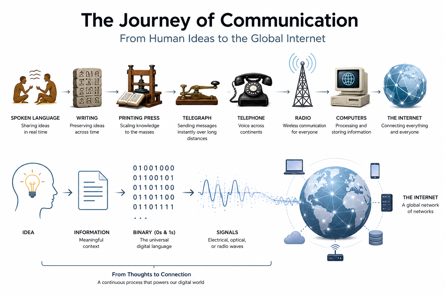










[…] are converted into bits, or how Shannon’s Information Theory dictates data limits, start with Volume I: The Architectural Foundations of Information before diving into the live protocol mechanics […]